SOYAL
ACCESS CONTROL SYSTEM
®
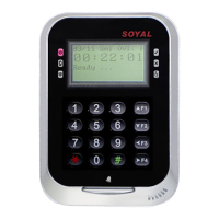
AR-725-E
V220916
- 2 -
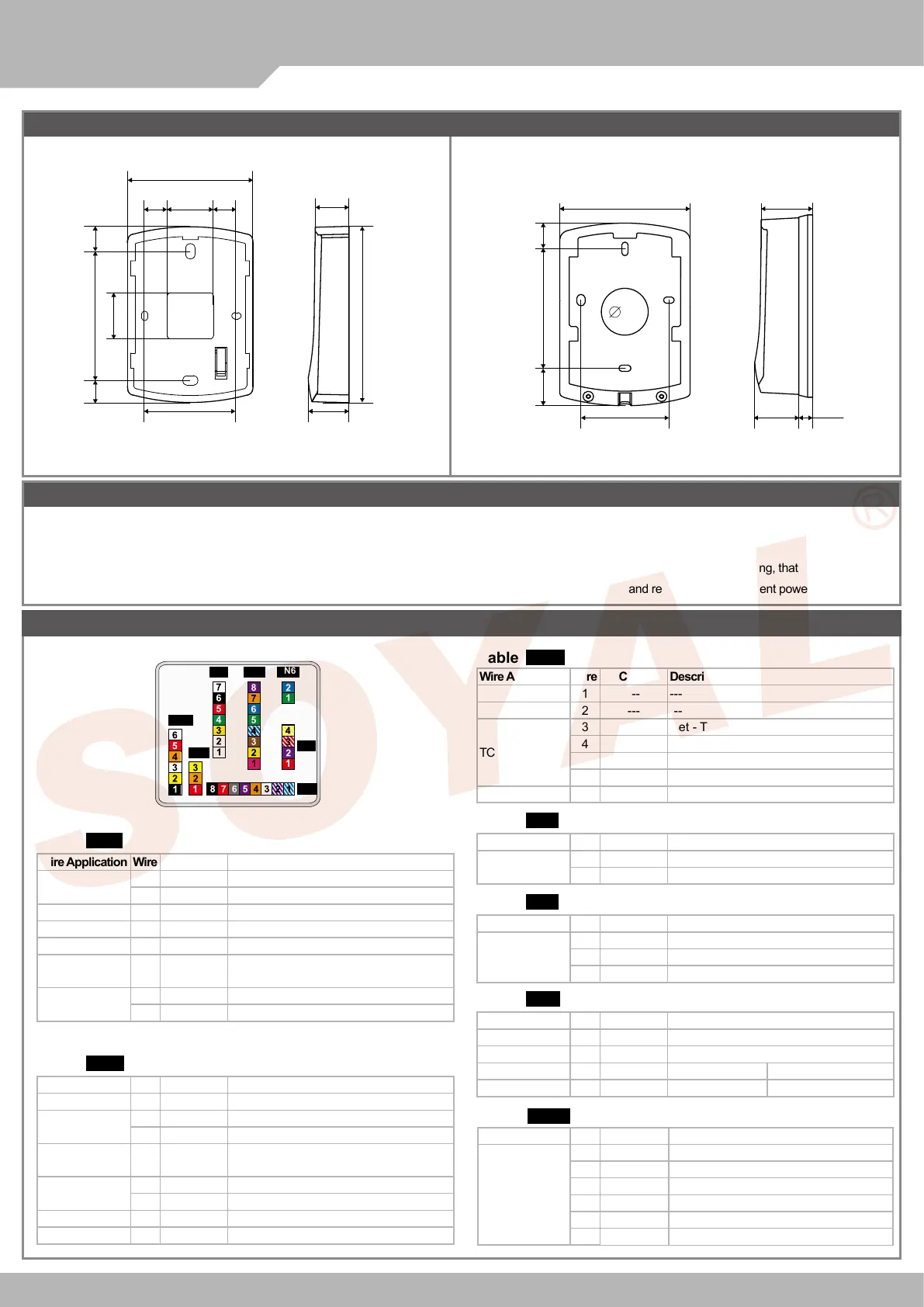
78.5
15 14.730
59.7
84
30
14.315.9
21.5
25.5
110
60
17.6 82.5 24.2
89
32
25.7
29.9
9.5
CN4
CN5CN7
CN8
CN6
CN3
CN11
Notice
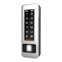
AR-725-E AR-725-E(Metal Housing)
1. Tubing: The communication wires and power line should NOT be bound in the same conduit or tubing.
2. Cable selection: Use AWG 22-24 Shielded Twist Pair to avoid star wiring. Use CAT5 for TCP/IP connection.
3. Power supply: Don’t equip reader and lock with the same power supply. The power for reader may be unstable when the lock is activating, that may make the
reader malfunction. The standard installation: Door relay and lock use the same power supply, and reader use independent power supply.
Wire Application Wire Color Description
Lock Relay
1 Blue White (N.O.)DC24V1Amp
2
Purple White
(N.C.)DC24V1Amp
Common-COM-Point
3 White (COM)DC24V1Amp
Door Sensor 4 Orange Negative Trigger Input
Exit Switch 5 Purple Negative Trigger Input
Alarm Relay 6 Gray
Transistor Output Max. 12V/100mA
(Open Collector Active Low)
Power
7 Thick Red DC 12V
8 Thick Black DC 0V
CN4Cable:
Wire Application Wire Color Description
Anti-Tamper
Switch
1 Red N.C.
2 Orange COM
3 Yellow N.O.
CN3Cable:
Wire Application Wire Color Description
Power 1 Red DC 12V
Output
Security trigger signal
2 Purple Security trigger signal Output
Arming 3 Red White Arming Output
WG mode: WG1 Output
Duress 4 Yellow White Duress Output
WG mode: WG0 Output
CN8Cable:
Wire Application Wire Color Description
1 --- ---
2 --- ---
TCP/IP Output
3 Yellow
Net - TX+
4 Green
Net - TX-
5 Red
Net - RX+
6 Black
Net - RX-
7 --- ---
CN7Cable:
Wire Application Wire Color Description
RS-485 for Lift
Controller
1 Thick Green RS-485(B-)
2 Thick Blue RS-485(A+)
CN6Cable:
Wire Application Wire Color Description
Beeper 1 Pink Beeper Output
5V/100mA, Low
LED
2 Yellow Red LED Output
5V/20mA, Max
3 Brown Green LED Output
5V/20mA, Max
Door Output 4 Blue White
Transistor Output Max. 12V/100mA
(Open Collector Active Low)
Wiegand
5 Thin Green Wiegand DAT: 0 Input
6 Thin Blue Wiegand DAT: 1 Input
WG Door
Sensor
7 Orange Negative Trigger Input
WG Exit Switch 8 Purple Negative Trigger Input
CN5Cable:
Connector Table
Wire Application Wire Color Description
TTL Port 1 Black DC 0V
2 Yellow
TX
3 White
TE
4 Orange
RX
5 Red DC 5V
6 --- ---
Cable: CN11
Optional:(Request to purchase AR-725L485 additionally)
Front View Front ViewSide view Side view