Report Number : TEC135
Issue : Two
Date : Mar 2006
Page : 7
Q601-30 3.0kW version
Care must be taken when installing a 3.0kW version of the SP601 controller. The
system is designed as 15A max. The element will draw 12.5A of current (at 240V)
leaving only 2.5A for a pump to flow water through the heater tube. For this reason the
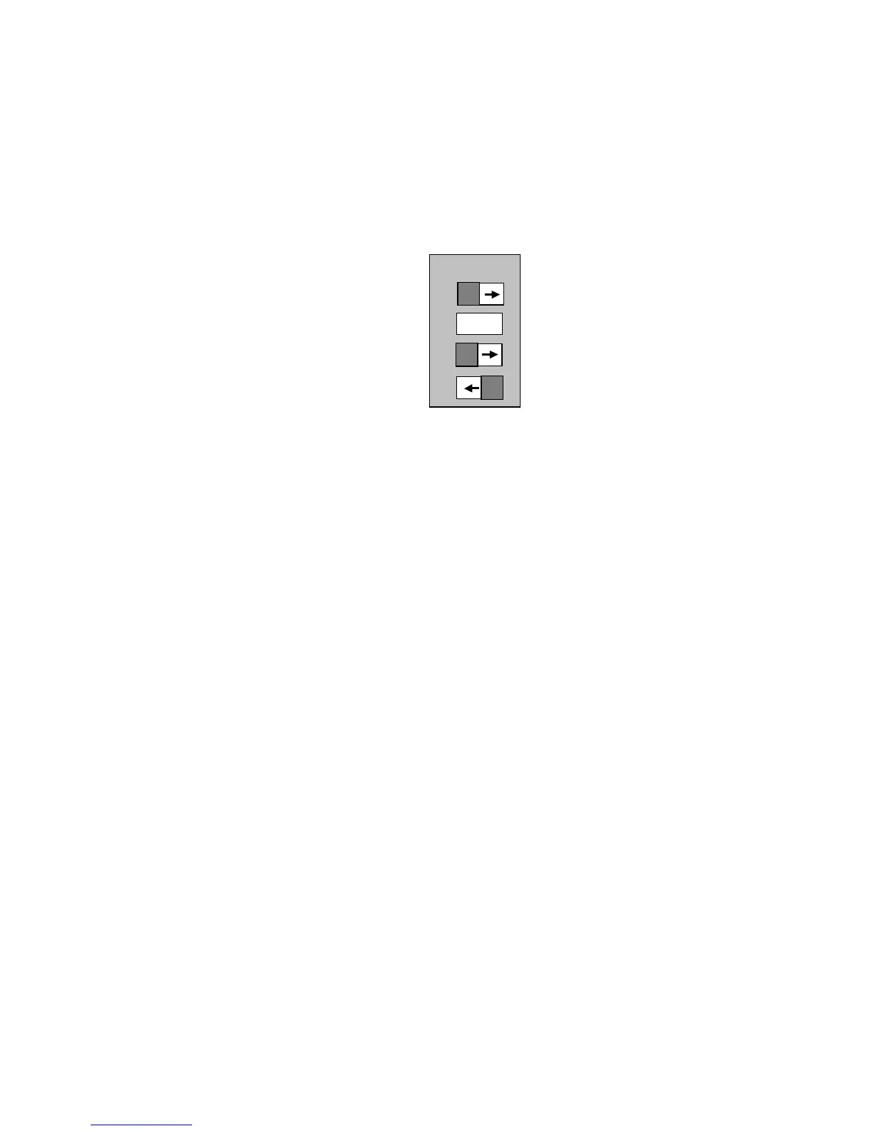
DIP switch settings must be:
The temp sensor can be either in element or in pool. With these DIP switch settings the
heater will only operate with the pump in low speed, keeping the system to 15A max. If
any other load is turned on, SPVSB or pump on high speed, the element will turn off.
The choice of two speed pump is limited to 2.5A on low speed. The pump and heater
currents can be out of phase, meaning that a pump with a current rating of 3A running
with a heater of 12.5A may be inside the 15A limit. To be sure, measure the current with
an ammeter. For this reason all of Spa-Quip’s two speed pumps will be suitable in this
configuration.
General Installation Instructions
Plumbing
1. The heater should be plumbed so the water flows past it from left to right when
horizontally mounted and bottom to top when vertically mounted. IMPORTANT: If
mounted vertically, the water sensor MUST be at the top.
2. When connecting pipework to the heater make sure the 'O' rings are properly seated
in the mac union fitting. Hand tighten only. Using tools will distort the fittings. Care
must be taken to ensure that all joins are inline, otherwise leaks may occur.
3. Make sure the controller is mounted securely so that vibration is minimised.
4. It is recommended that the pipework has shut off valves so the controller and pump
can be removed for service without loss of water.
5. Pressure test the installation to check for leaks.
6. Support all pipework to prevent sagging and to prevent movement when pumps turn
on or off.
7. Insulate all pipework to decrease heat loss.
Refer to the ‘Circulation pump’ and ‘Ozone system’ sections of this manual for
information regarding the installation of those systems.