Spanco.com • 1-800-869-2080 •
Spanco
®
A-Series Aluminum Gantry Crane 7
Promise to Perform Industries, Inc.
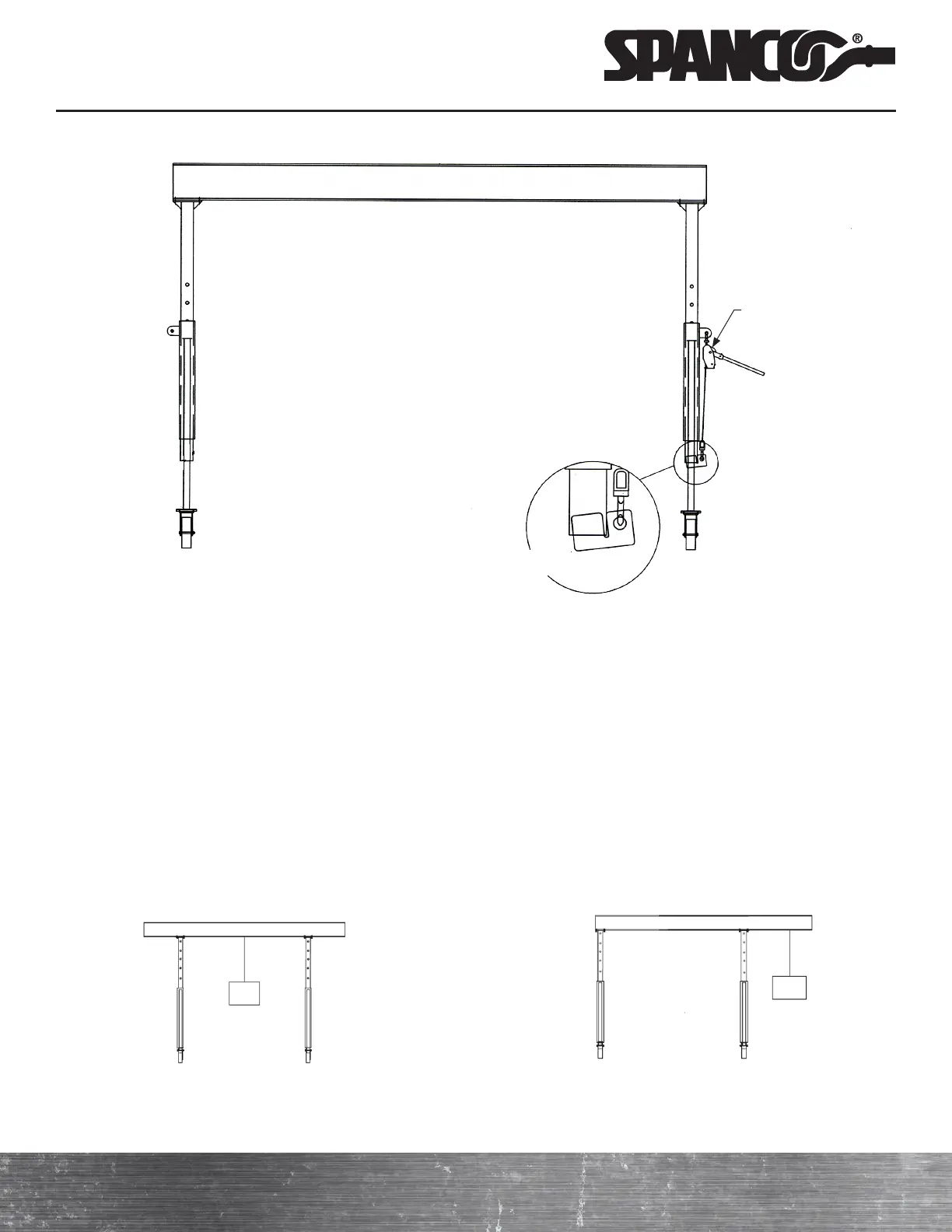
Lug-All Winch Kit with Adapter Lug
Leg support removed for clarity
Winch kit with adapter lug for all A-Series Aluminum ALU
Gantry Cranes:
03-015-.5-ALU 1/2 Ton
03-015-1SHORT-ALU* 1 Ton
03-015-1TALL-ALU** 1 Ton
03-015-2-ALU 2 Ton
03-015-3-ALU 3 Ton
*Maximum height under boom of eight feet.
**Maximum height under boom greater
than eight feet.
Lug-All winch
03-015
Correct Incorrect
ADJUSTING THE GANTRY SPAN
a ) Adjust the gantry to its lowest position. The beam is clamped in place at each end with four beam clamps (15).
Using an overhead hoist or lift truck, attach lifting straps to the beam to support the crane. Loosen the bolts which
hold the clamps and move the legs to the desired position.
b ) Do not move the legs (A-frames) inward more than the minimum clear span. The minimum clear span is equal to
the distance between the casters (tread width) or one-half the overall beam length—whichever dimension is greater.
See the minimum clear span chart on page eight for the minimum clear span dimensions for standard Spanco
Aluminum Gantry Crane models.
c ) After adjusting the span as desired, re-tighten all eight bolts (11) securely. Move both legs when adjusting the span
so one end of the beam does not hang over more than the other end. Do not suspend a trolley or load from the
cantilevered ends of the beam.