Spanco.com • 1-800-869-2080 •
Spanco
®
A-Series Aluminum Gantry Crane 3
Promise to Perform Industries, Inc.
3. Attaching the Swivel Locks to the Caster Assemblies
Refer to A-Series Aluminum Gantry Crane Assembly Drawing for Steps A Through F
a ) The swivel lock ships zip tied to the caster assembly for polyurethane casters.
b ) Insert the pin on the swivel lock into the groove beneath the caster plate on the caster assembly.
c ) Open the pin on the swivel lock by pulling and spinning the ring to fit into the groove at the end of the swivel lock.
d ) Using two bolts, washers, and nuts, bolt the swivel lock to the caster plate.
e ) Using a wrench and a socket and ratchet, tighten the swivel lock bolts to 257 foot-pounds.
f ) Repeat steps b) through e) to install the remaining swivel locks.
4. A-Frame Assembly
Refer to A-Series Aluminum Gantry Crane Assembly Drawing for Steps A Through C
WARNING: Crane parts are heavy. Exercise caution when handling all parts during assembly, adjustment, and
disassembly processes.
a ) Select an area under an overhead hoist, or where a lift truck can be used to raise the beam. Be sure there is no
machinery or clutter nearby that will obstruct free movement. All personnel should be wearing applicable safety
gear, such as hard hats, steel toe shoes, and safety glasses.
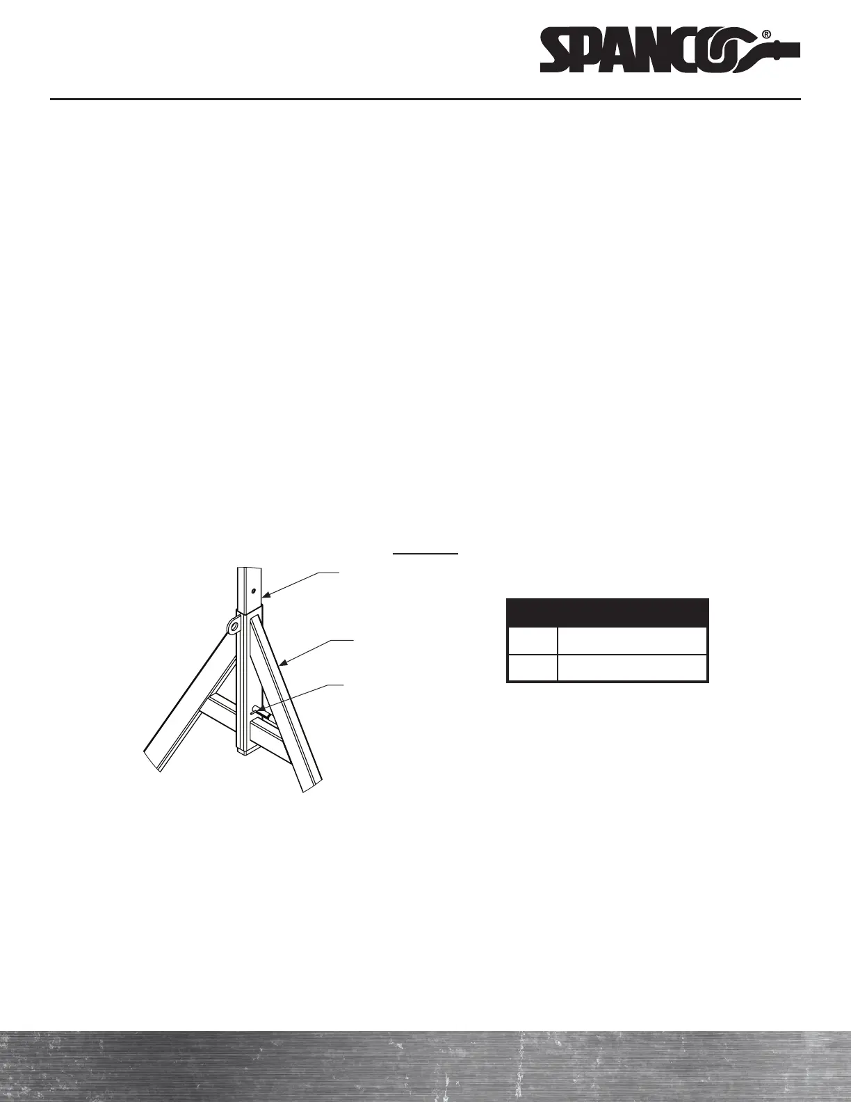
b ) Lay both A-frames (3) flat on the floor. Slide an upright tube (2) into the top of the center tube of each A-frame.
c ) Engage the load pin to secure each upright tube in its lowest position. Ensure that the load pin is fully engaged.
Detail “A”
ITEM DESCRIPTION
2 Upright Tube
3 A-Frame
2
3
Load Pin
5. Attaching the Caster Assemblies to the A-Frame Assemblies
Refer to A-Series Aluminum Gantry Crane Assembly Drawing for steps A through F
a ) Align the holes in the A-frame assembly with the holes in the caster assembly’s top plate.
b ) Per Detail “B,” insert a bolt (10) through the aligned holes in the A-frame and the caster assembly so that the bolts
(10) extend from the A-frame through the caster assembly’s top plate.
c ) Per Detail “B,” place a flat washer (8), lock washer (7), and hex nut (9) on each bolt (10) so that the lock washer (7)
is between the flat washer (8) and hex nut (9). Torque all nuts (9) to 23 foot-pounds.
d ) Repeat steps e) through g) to attach the remaining caster assemblies to the caster frame assemblies.