Promise to Perform Industries, Inc.
A-SERIES ALUMINUM GANTRY CRANE MANUAL
10 Spanco
®
A-Series Aluminum Gantry Crane
• 1-800-869-2080 • Spanco.com
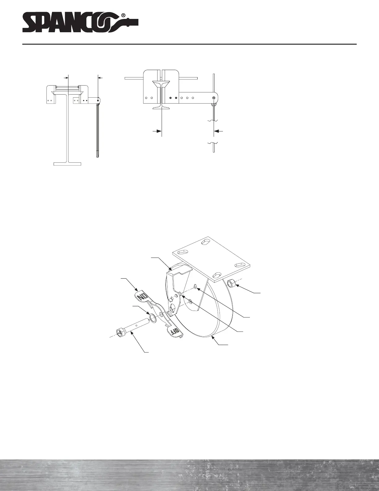
Brake shoe (leg)
Brake pedal
Cup spring washer
Shouldered axle bolt
Wheel
Shoe guide pin
Brake slot
Hex nut
2. Top-Lock Wheel Brake Assembly
Some polyurethane casters ship with their wheel brakes already attached. If your wheel brakes were shipped loose,
follow steps a) through h) to attach the wheel brakes.
Refer to the Wheel Brake Assembly Drawing for Steps A Through H
Wheel Brake Assembly Drawing
a ) Using a 3/4-inch wrench and 3/4-inch socket and ratchet, unbolt the caster stud and remove the nut, bolt, washer,
and caster.
NOTE: If the spacers fall out of the caster, reinsert them into the caster holes.
b ) With the top of the brake shoe facing towards the caster assembly, insert the guide pin on the brake shoe into the
brake slot on the caster assembly.
c ) Using a screwdriver, slightly bend the brake shoe tab so that the brake shoe guide pin and brake shoe tab fit
properly.
d ) With the brake pedal tabs pointed away from the caster assembly, line up the hole on the brake pedal with the hole
on the brake shoe. “On” and “Off” on the brake pedal tabs should be visible when the caster is mounted to the
system.
approx. 10
inches
approx. 10
inches
NOTE: Position the Arm Plate so that
the tagline is approximately 10 inches
from the face of the beam.
Figure 3