Promise to Perform Industries, Inc.
A-SERIES ALUMINUM GANTRY CRANE MANUAL
4 Spanco
®
A-Series Aluminum Gantry Crane
• 1-800-869-2080 • Spanco.com
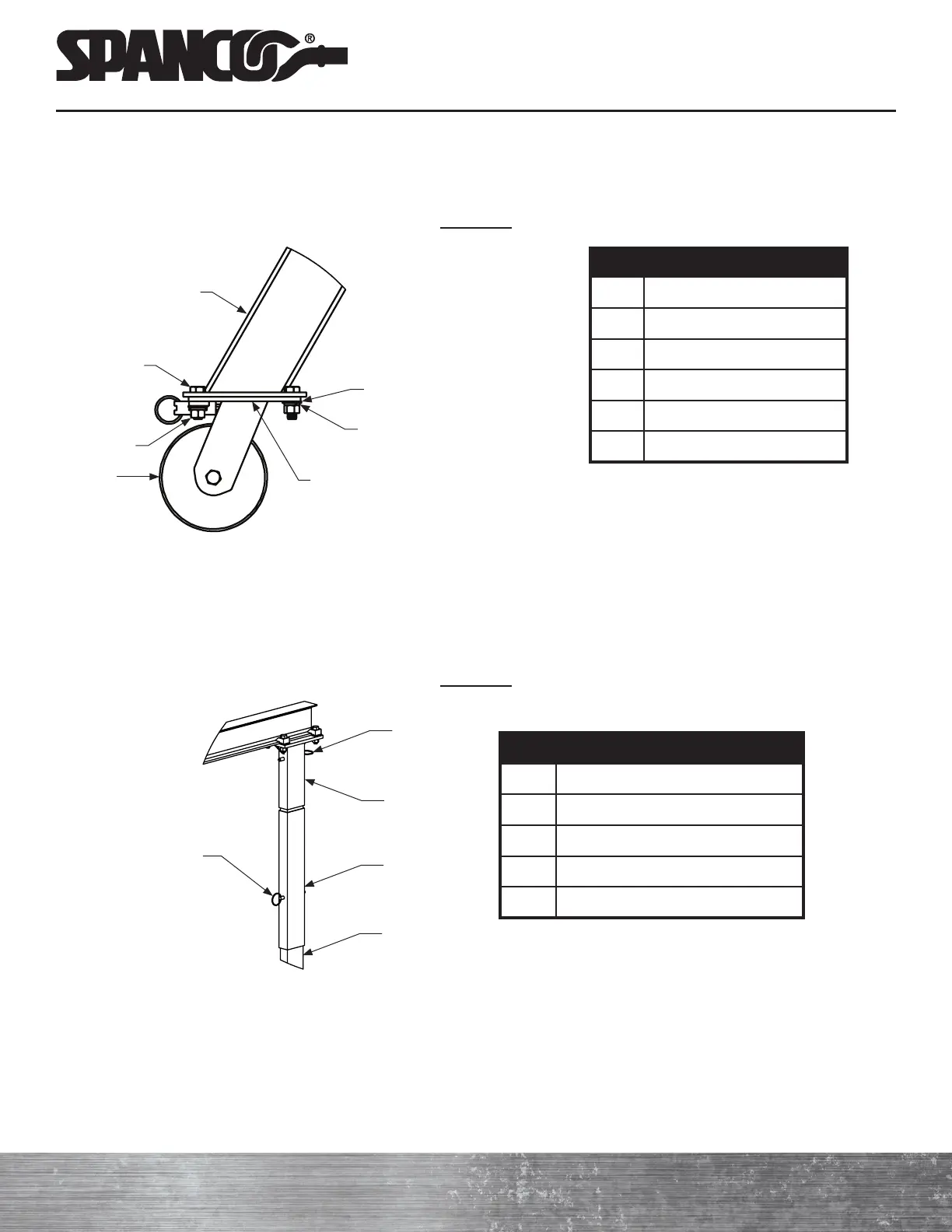
ITEM DESCRIPTION
3 A-Frame
6 Caster
7 Lock Washer
8 Flat Washer
9 Hex Nut
10 Hex Bolt
NOTE: Torque all wheel stud nuts to
23 foot-pounds only.
e ) Test the caster brakes and swivel locks to ensure they function properly.
f ) Lock the caster wheels in position parallel to the A-frame to prevent the frame assembly from rolling away when
lifted to the upright position.
Detail “B”
Caster Assembly's
Top Plate
10
9
8
7
6
3
6. Beam Assembly
Refer to A-Series Aluminum Gantry Crane Assembly Drawing for Steps A Through K
a ) Per Detail “E,” place the optional two-foot extensions (16) onto the upright tubes (2), if required, and secure with
one pair of hitch pins (5).
Detail “E”
ITEM DESCRIPTION
2 Upright Tube
3 A-Frame
4 Top Plate
5 Hitch Pin
16 Optional Two-Foot Extension
b ) Per Detail “D,” place one top plate (4) onto each upright tube (2) or two-foot extension (16). Secure each top plate
with a hitch pin (5).
c ) Lift the beam to the gantry’s minimum height. Light aluminum beams may be raised by hand. Use appropriate
lifting equipment and secure rigging to lift larger, heavier beams. Be sure that the holes in the beam flange are on
the bottom, and that the capacity label is right-side-up and legible.
5
5
4
2
16