Spanco.com • 1-800-869-2080 •
Spanco
®
A-Series Aluminum Gantry Crane 5
Promise to Perform Industries, Inc.
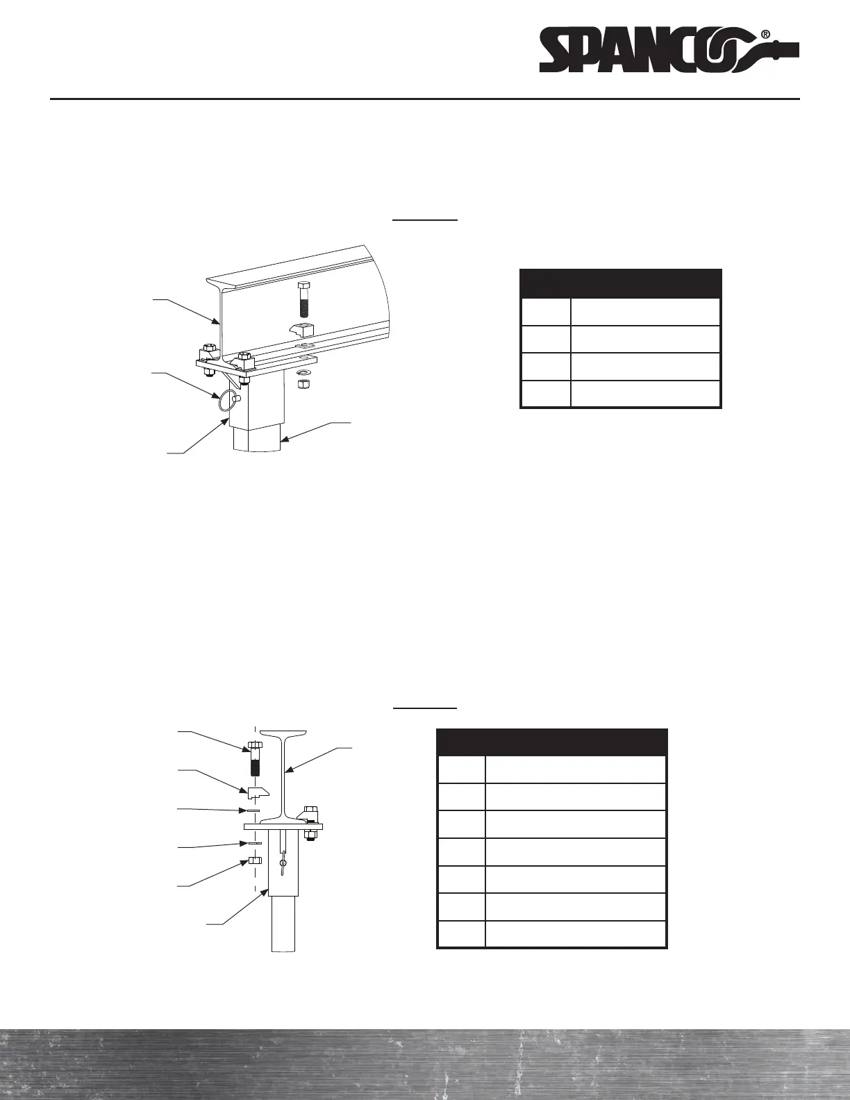
ITEM DESCRIPTION
1 Beam
2 Upright Tube
4 Top Plate
5 Hitch Pin
d ) Install the hoist trolley according to the manufacturer’s recommendations onto the lower flange of the beam and
secure it in the middle of the span.
e ) Lift one A-frame assembly (3) into position under one end of the beam, ensuring that the lifting lug is on the
outside of the A-frame, not facing the beam.
Detail “D”
NOTE: Torque 5/8-inch bolts to 108
foot-pounds. Torque 3/4-inch bolts to
210 foot-pounds.
2
4
1
5
f ) Per Detail “C,”
insert a bolt (11) through a beam clamp (15) and a clipped washer (14)
. Ensure that the flat edge of
the clipped washer (14) will face away from the beam.
g ) Per Detail “C,” insert the bolt (11) with the attached beam clamp (15) and clipped washer (14) through the holes in
the top plate (4) and position the beam clamp so it holds onto the lower flange of the beam (1).
h ) Per Detail “C,” securely tighten a lock washer (12) and a hex nut (13) onto the hex bolt (11).
i ) Repeat steps f) through h) for all four holes in the top plate (4). Adjust the beam clamps (15) as needed by tightening
or loosening the nuts (13) until the beam clamps sit properly on the lower flange of the beam (1).
j ) Repeat steps e) through i) to attach the second top plate (4).
k ) Ensure that all beam clamps (15) are installed horizontally and level within plus or minus five degrees. Tighten all
hex nuts (13) to the correct torque value.
Detail “C”
ITEM DESCRIPTION
1 Beam
4 Top Plate
11 Hex Bolt
12 Lock Washer
13 Hex Nut
14 Clipped Washer
15 Beam Clamp
11
13
12
14
15
NOTE: Item 14 quantity varies with
gantry model.
4
1