| Description | 8
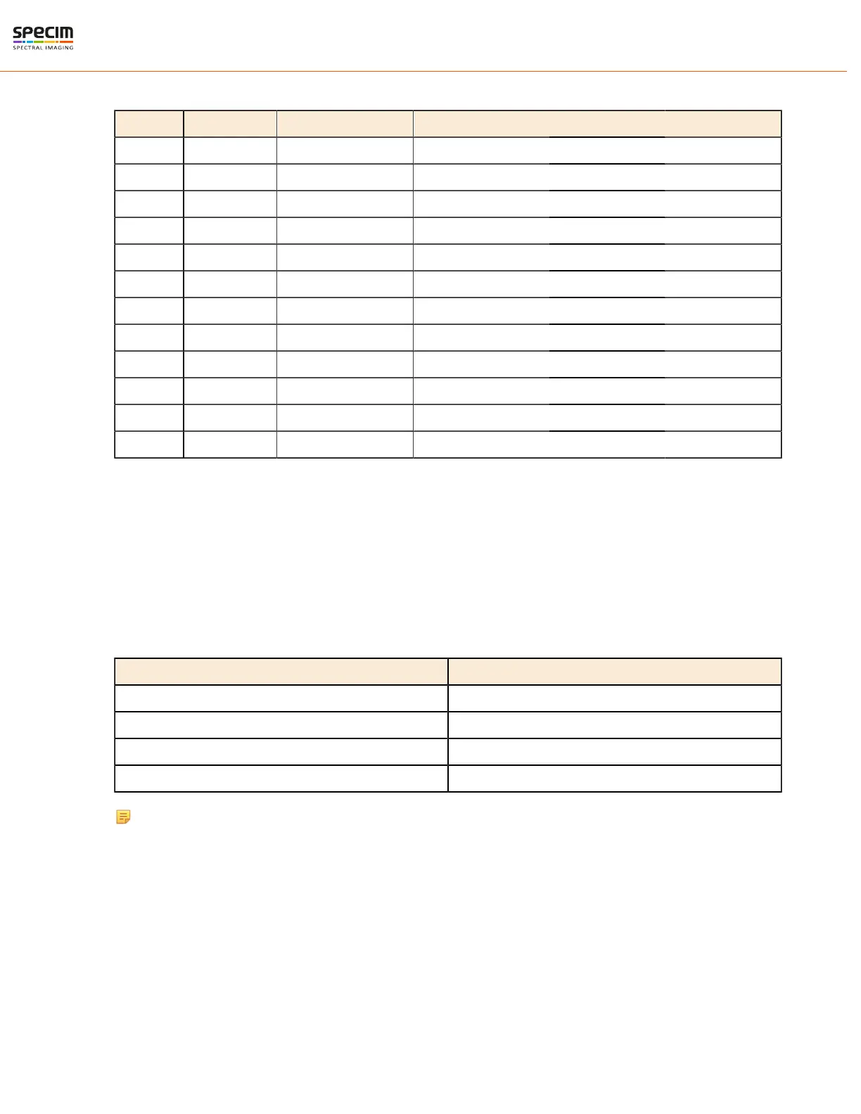
Table 1: Power Connector Pin-out
pin # I/O Type Name Description
1 O ISO_OUT0 General purpose Output 0, single-ended output
2 O ISO_STROBE Default Strobe out, single-ended output
3 O RESERVED Reserved, do not connect
4 PWR CAMERA_GND Camera GND, 0V
5 PWR CAMERA_PWR Camera Power 12V (+/- 10%)
6 PWR ISO_GND I/O GND, 0V
7 I ISO_IN0 General purpose input 0
8 I ISO_TRIGGER Default Trigger in (5-15 V)
9 O RESERVED Reserved, do not connect
10 O RESERVED Reserved, do not connect
11 O RESERVED Reserved, do not connect
12 O RESERVED Reserved, do not connect
Camera Link Camera External Interfaces
Camera Link Connector
There is a standard MDR 26-pin camera link connector on the back panel of the camera for camera control signals
and serial communication.
For more information on Camera Link connector, refer to Camera Link interface standard specifications.
LED Indications
There is one green LED in the FX camera back panel.
LED Status
Not lit Power off
Blinking green in startup Starting up
Stable green Power on, not recording
Blinking green Recording, data being transferred
Note: Camera blinks briefly during startup. This period can be very short and therefore easy to miss.
GigE Camera External Interfaces
GigE Connector
There is a standard GigE M12 X-coded Ethernet connector on the back panel of the camera for camera control signals
and serial communication.
All rights reserved - Specim, Spectral Imaging Oy Ltd.