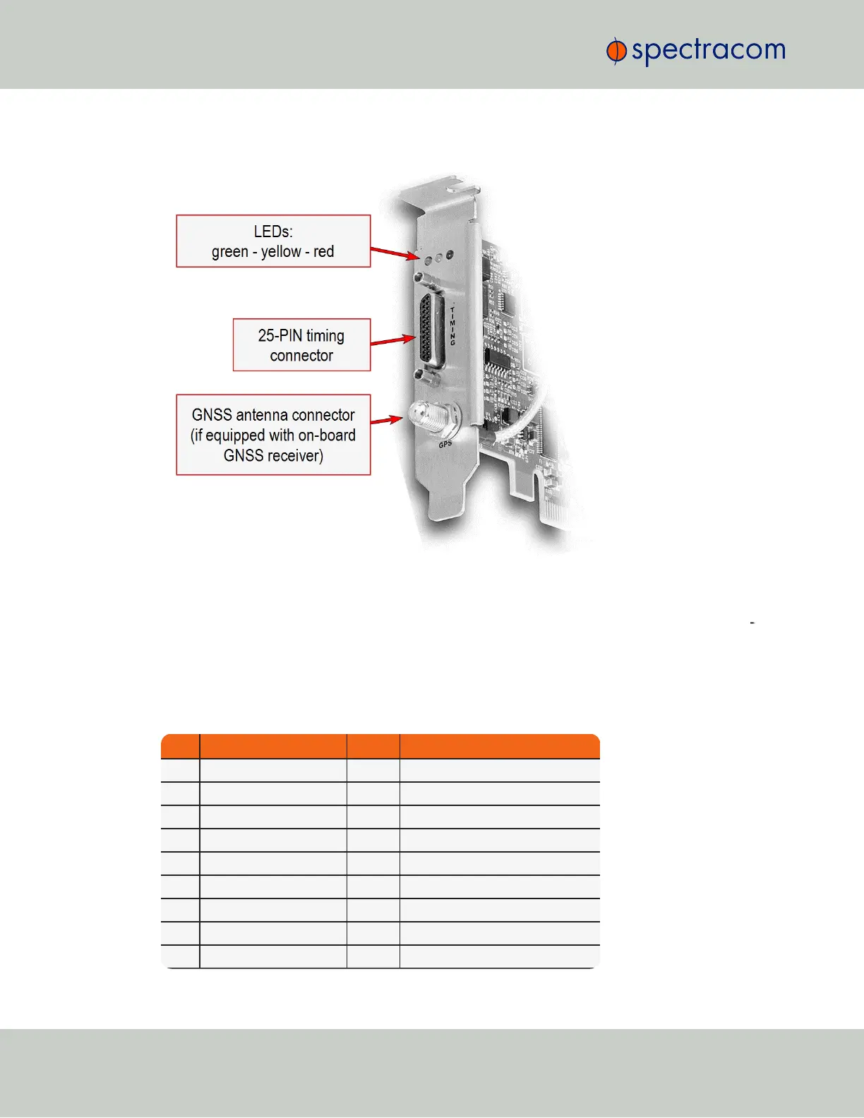
The illustration below shows the functional elements of the TSync-PCIe card:
Figure 4-1: TSync-PCIe board
The timing interface connector supports all of the input and output references, and GPIO. It con
sists of a 25-pin Micro D-sub plug.
4.1 Timing Connector Pinout
Pin Signal Pin Signal
1 GPIO Output 2 14 GPIO Output 3
2 Ground 15 Ground
3 GPIO Output 0 16 GPIO Output 1
4 GPIO Input 2 17 GPIO Input 3
5 Ground 18 Ground
6 GPIO Input 0 19 GPIO Input 1
7 External 1PPS Input 20 1PPS Output
8 Ground 21 Ground
9 IRIG AM Output 22 10-MHz Output
18
CHAPTER 4 • Instruction Manual XYZ Rev. R
4.1 Timing Connector Pinout