Pin Signal Pin Signal
10 IRIG AM Input + 23 Ground
11 IRIG AM Input - 24 IRIG DCLS Input -
12 IRIG DCLS Output - 25 IRIG DCLS Input +
13 IRIG DCLS Output + 26 Ground
Table 4-1:
Timing connector pinout
For additional information refer to "Accessories" on page38.
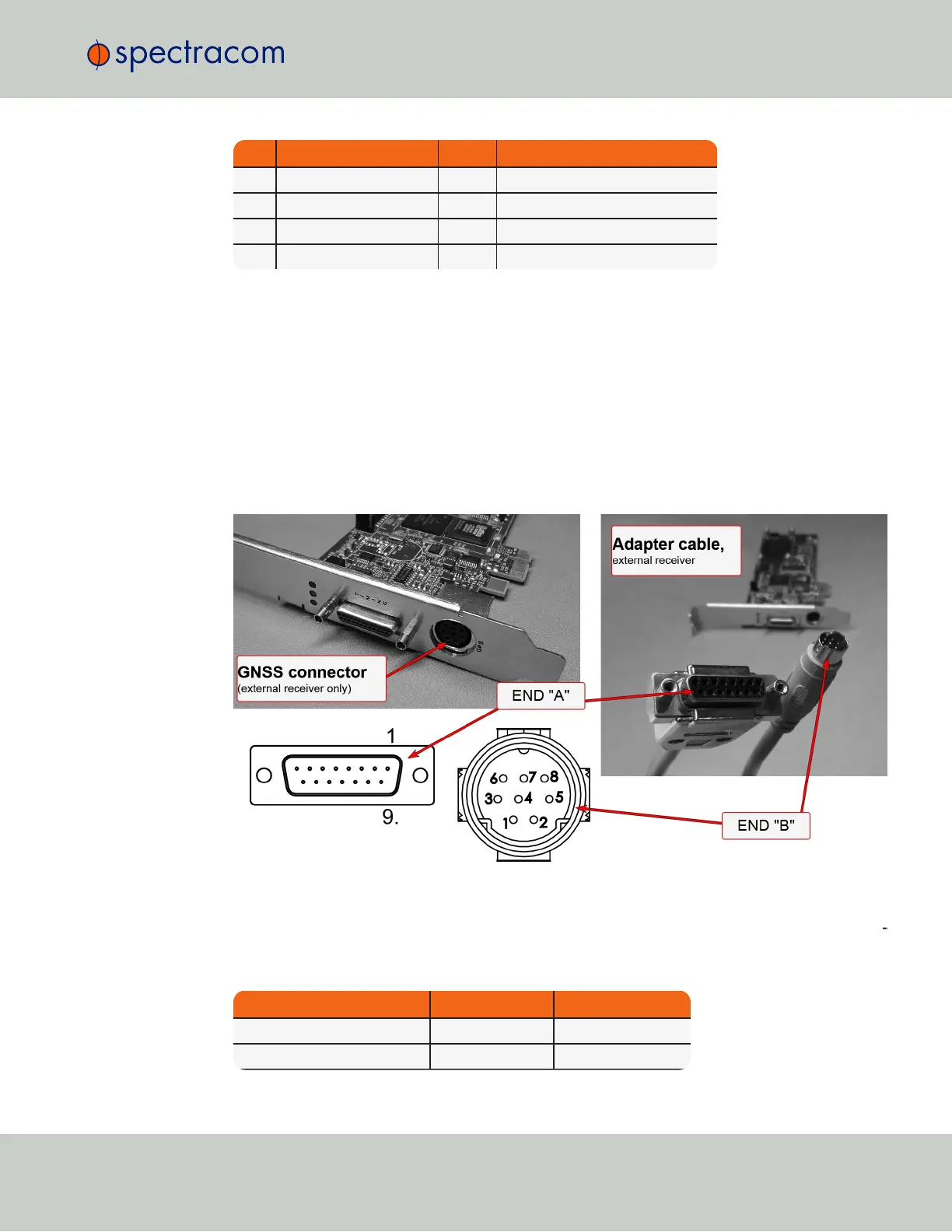
4.2 External GNSS Connector Pinout
If your TSync-PCIe card is configured for an external GNSS receiver, a Mini-DIN-8 connector is
used for signal transmission. The provided adapter cable (see illustration below) connects the
cable of the external receiver with the GNSS connector of the TSync-PCIe card.
Figure 4-2: GNSS receiver adapter cable
See table "Adapter pinout, ext. GNSS receiver" on the next page for adapter pinout ref
erence.
Signal END "A" END "B"
+12 V 3 1
GND 5 2
4.2 External GNSS Connector Pinout
CHAPTER 4 • Instruction Manual XYZ Rev. R
19