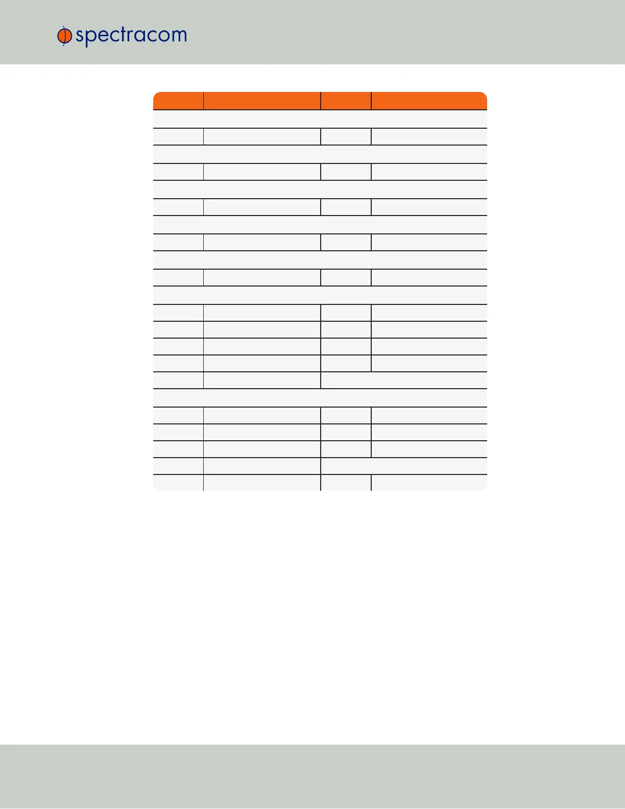
Pin Signal Pin Signal
P3—10MHz Output (BNC Female)
1 10MHz Output BS Ground
P4—1PPS Output (BNC Female)
1 1PPS Output BS Ground
P5—IRIG AM Input (BNC Female)
1 IRIG AM Input + BS IRIG AM Input -
P6—IRIG AM Output (BNC Female)
1 IRIG AM Output BS Ground
P7—1PPS Input (BNC Female)
1 External 1PPS Input BS Ground
P8—GP Input (DB-9 Female)
1 GPIO Input 0 7 Ground
2 GPIO Input 1 8 Ground
3 GPIO Input 2 9 Ground
4 GPIO Input 3 BS Ground
6 Ground
P9—GP Output (DB-9 Female)
1 GPIO Output 0 7 Ground
2 GPIO Output 1 8 Ground
3 GPIO Output 2 9 Ground
4 GPIO Output 3
6 Ground BS Ground
Table 7-2:
Pinout, premium breakout cable (unspecified pins are not connected in the cable)
7.2.3 Basic Breakout Cable
The basic breakout cable breaks out a subset of features from the 26-pin timing connector to
separate BNC and DB-9 connectors for use. The basic breakout cable supports the following
features: External 1PPS Input, IRIG AM Input, IRIG DCLS Input, IRIG AM Output, (1) GP Input, (2)
GP Outputs.The pinout of the connector is depicted below:
7.2 Accessories
CHAPTER 7 • Instruction Manual XYZ Rev. R
41