24
5.4 Probe wiring
The maximum cable length for all probes is 100 m (9990 and 999.0 ranges), 10 m (9.990 range)
or 30 m (99.90 range). All cables must be of the same gauge.
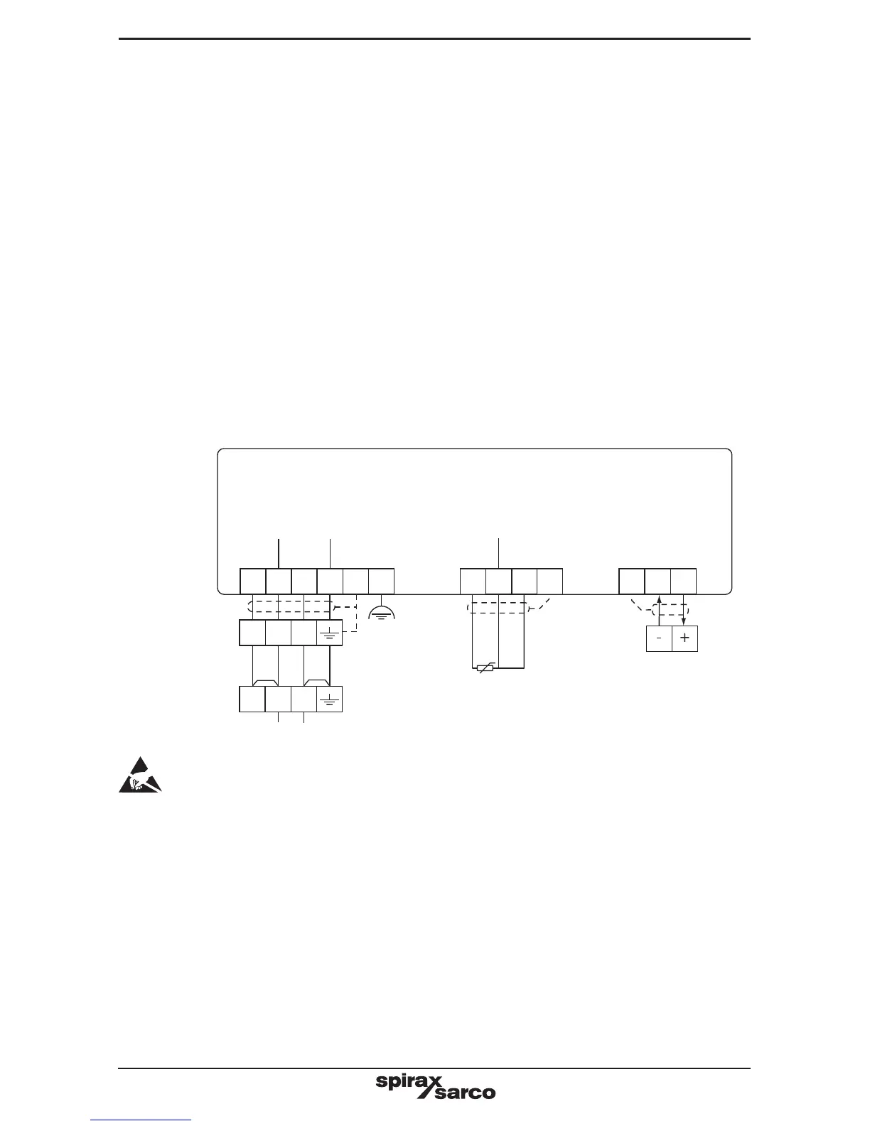
Fig. 15 Signal circuit
Back
Connect
to a clean
local earth
in the
panel
CP30 and CP32
conductivity
probe
CP10
conductivity
probe
Drive
Drive
Com
sense
Com
Sense
Scn Com
White
Red
Red
Or red
tracer
Pt100
Red Blue (Internally connected to probe body)
0/4 - 20 mA
Output
Notes: Do not connect terminal 54 to any other earth. Ensure resistance from the probe
body to the pipework / boiler shell is less than 1 ohm.
E = functional earth. Connect these pins to earth local to the panel.
5.3 Signal wiring notes
An earth current loop is created if a wire or screen is connected between two earth points
that are at different potential (voltage). If the wiring diagram is followed correctly, the screen
will only be connected to the earth at one end.
The earth terminal is a functional earth rather than a protective earth.
A protective earth provides protection from electric shock under a single fault condition. This
product has double insulation and therefore does not require a protective earth. A functional
earth is used in order for the product to operate. In this application, the earth is used as a
sink or drain for any electrical interference. The earth terminal must be connected to a local
earth in order to conform to the EMC directive.
View from the top
Front
Drive
sense
E
56 57 58 59
Screen
50 51 52 53 54 55 60 61 62
Screen
Screen