IM-P337- 6 9 EMM Issue 2
23
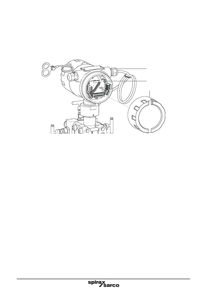
Wiring compartment and cable entry
The MVT10 contains an integral wiring compartment, located at the rear of the enclosure. To access the
compartment, loosen the small grub screw and unscrew the rear cover.
A M20 x 1.5 female conduit entry is available for power and signal wiring. The product comes fitted with a
cable gland which is suitable for one cable with a 5-12 mm diameter. Two or more cables can be installed
into this gland, but will compromise the products IP65 ingress protection.
Unused apertures shall be closed with suitable blanking plugs. If conduit seals are used, they must be
installed within 457 mm (18") of the enclosure.
Grub screw
Cover
Cable gland
Terminals specification:
All cables must be screened and terminated as per wiring diagram.
Wire gauge/type: 0.25 – 1 mm
2
(24 to 16 AWG), stranded
Terminal torque rating: 0.2 - 3 Nm (2 - 3 lb/in)
Number of wires per terminal: 1
Wire stripped length: 0.7 mm (0.25 in)
The wiring connections are identified beside the terminal plugs.
Install wiring in accordance with:
IEC 60364 - Low-voltage electrical installations.
BS 6739 - Instrumentation in Process Control Systems: Installation design and practice or local equivalent.
National and Local Electrical Code (NEC) or Canadian code (CEC) for the US and Canadian markets.
Note: use NEC Class 1 wire with a temperature rating greater than 75 °C. If the cable is to be exposed to a
higher temperature, then a higher temperature rating needs to be selected.
It is important that the cable screens are connected as shown in order to comply with the electromagnetic
compatibility requirements.
All external circuits must meet and maintain the requirements of double/reinforced installation as stated in
IEC 60364 or equivalent.
Earthing note:
An earth current loop is created if a wire or screen is connected between two earth points that are at different
potential (voltage). If the wiring diagram is followed correctly, the screen will only be connected to the earth
at one end.
The earth terminal is a functional earth rather than a protective earth.
A protective earth provides protection from electric shock under a single fault condition. This product has
double insulation and therefore does not require a protective earth. A functional earth is used in order for
the product to operate. In this application, the earth is used as a sink or drain for any electrical interference.
The earth terminal must be connected to a local earth in order to conform to the EMC directive.
Fig. 18