IM-P343-22 CH Issue 2
4
2. Options
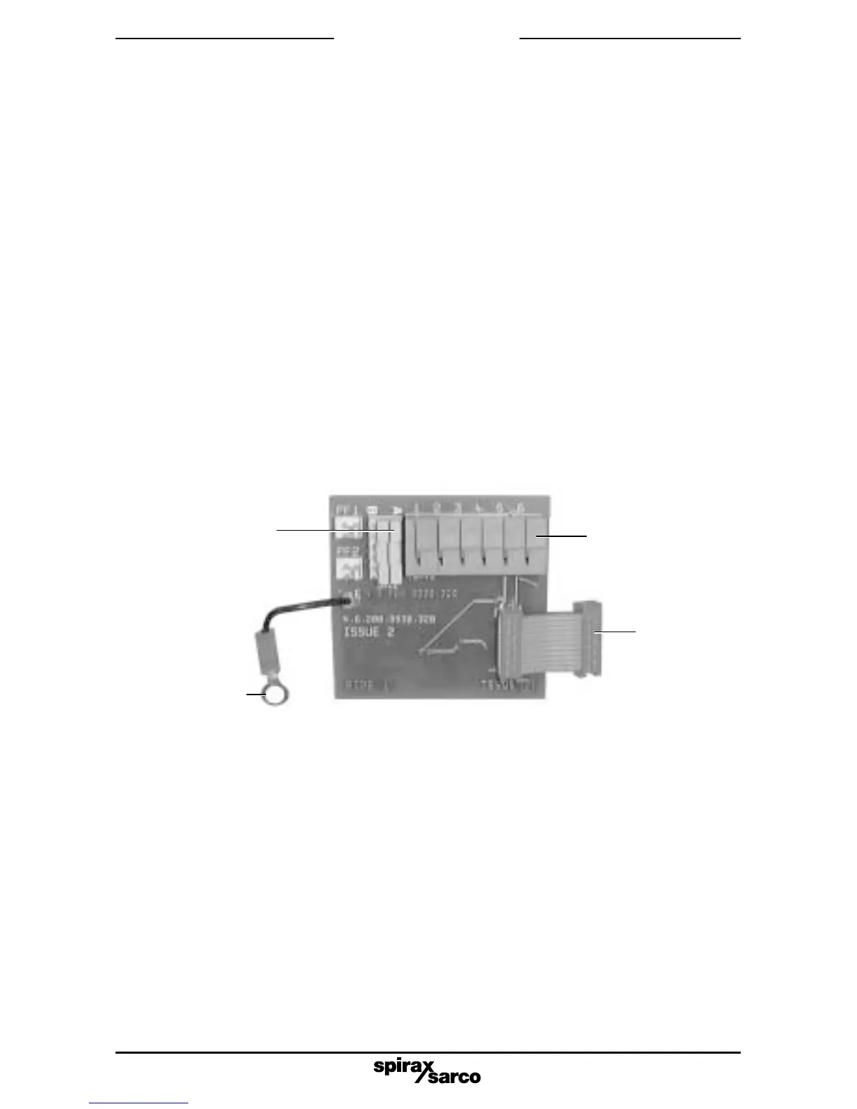
Fig. 1 Options PCB
2.1 Available options
2.1.1 Software travel switches
Two software configured travel switches supplied on a standard options PCB.
The travel switch 1 (TS1) is normally open and the travel switch 2 (TS2) is normally closed.
2.1.2 Pepperl and Fuchs mechanical travel switches
Two mechanical proximity travel switches plus standard options PCB board.
2.1.3 4 - 20 mA retransmit
4 - 20 mA retransmission of actual valve position (as measured in autostroke - AUTOS) plus
standard options board having two software configured travel switches or connections for Pepperl
and Fuchs mechanical proximity travel switches.
Note: Options boards are individually electrically isolated and externally powered.
2.2 Fitting the options board
2.2.1 Firstly set the yellow slide switch as follows (refer to Fig. 1):
If the options PCB is used for software configured travel switches, set all elements of the
yellow slide switch SW1 to position 'A'. Prepare the ribbon cable by ensuring that the
connector is at right angles to the options PCB, ready for insertion into the main PCB
socket (refer to Fig. 1).
SW1 switch set
in position A
Earth
connection
fitted with
4 - 20 mA
option only
Terminal block
Ribbon
cable
connector
2.2.2 To gain easy access for fitting the options board remove the indicator disc domed nut,
washer and travel indicator disc.