IM-P343-22 CH Issue 2
5
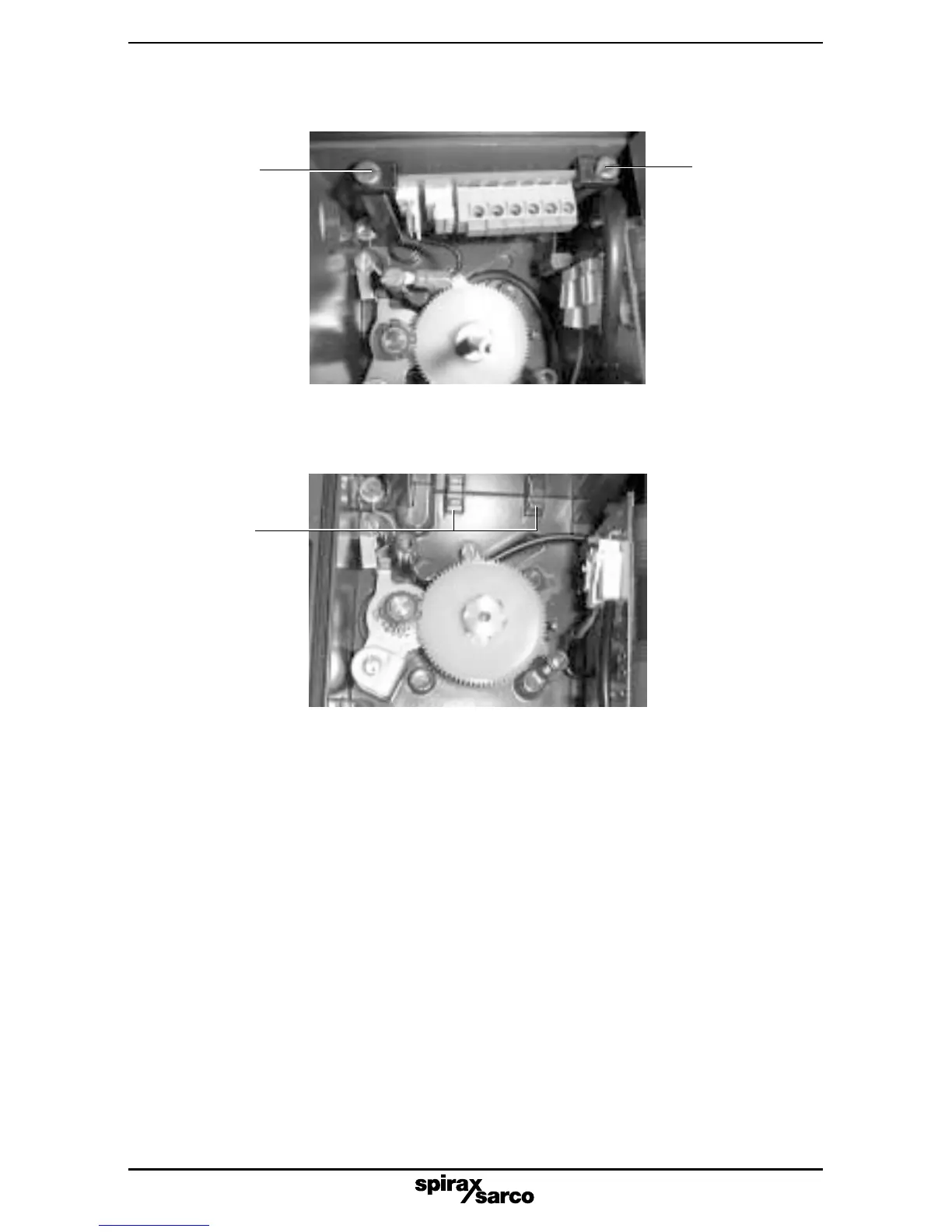
Fig. 3
2.2.4 Locate the edge of the options PCB in the two cast-in location lugs at the base of the
SP2 case (refer to Fig. 3).
2.2.5 Push the connector on the ribbon cable into the socket on the main PCB.
Note: this should be done with light finger pressure only, do not apply force.
Cast in
location
lugs
Fig. 2
Retaining
clamp
Retaining
clamp
2.2.3 Loosen the two plastic retaining clamps within the SP2 housing (refer to Fig. 2).