IP Paging Microphone User Manual
6
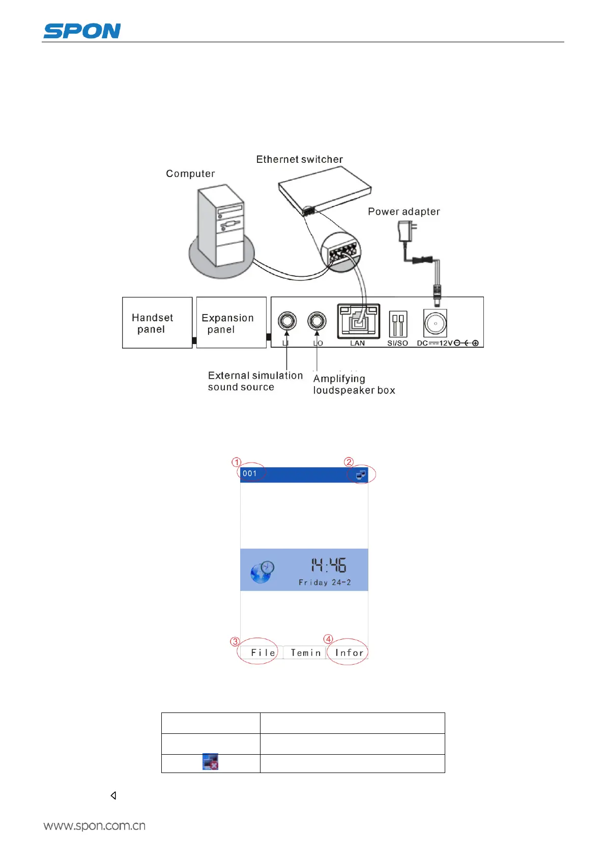
Wiring
(1)Make one port of the power adapter connect with theIP Paging Microphone DC12V port, and the other Port connect
with the power socket.
(2)Make one port of the Ethernet line connect with the IP Paging Microphone LAN port, and the other port connect with
the switcher.
Interface Description
After the power on for 15 seconds to enter the main interface successful, it will display the time and date information.
Main interface
①IP paging microphone ID
②Terminal status icon
Terminal login the server
Cables is not properly connect
③File: Display audio file list
Press “ ” or【File】 key to enter the list of file broadcasting. Press the corresponding shortcut key to the right of the