6.2 Debug
By default, the debug connector is not assembly on the MB1803B-01. If necessary, the connector should be soldered. By this
way, that allows to select the type of connector STDC14 or MIPI10. The foot print is compatible with the both connectors.
Figure 6 CN3 assembly for debug connector
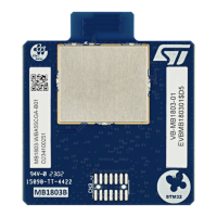
It is also necessary to add some components on the bottom side of the MB1803. On the table4, there are
the value of the components and the Figure7 shows the location of these components.
Table 4. Components to add to support STLin-V3PWR config.
R2, R3, R4, R5, R6, R7, R8, R9