6.7 MIPI10/STDC14 connector pinout
7.12.1 Description
On the MCU RF Board, there is a footprint for direct debug. This footprint is compatible with MIPI10 and STDC14
connectors. STDC14 is an extension of the MIPI10 connector.
By default, on this footprint (CN3), the connector is not assembly. If some features not available on the
STlinkV3EC embedded on MB1801, it’s possible to solder a MIPI10 or STDC14 connector. That allows to use an
external debugger, Nevertheless, it will be necessary to disconnect the SWD (open SB15 and SB17 on the
MB1801).
Example of connector compatible with this footprint :
- MIPI10 : FTSH-105-01-L-DV-K (SAMTEC)
- STDC14 : FTSH-107-01-L-DV-K (SAMTEC)
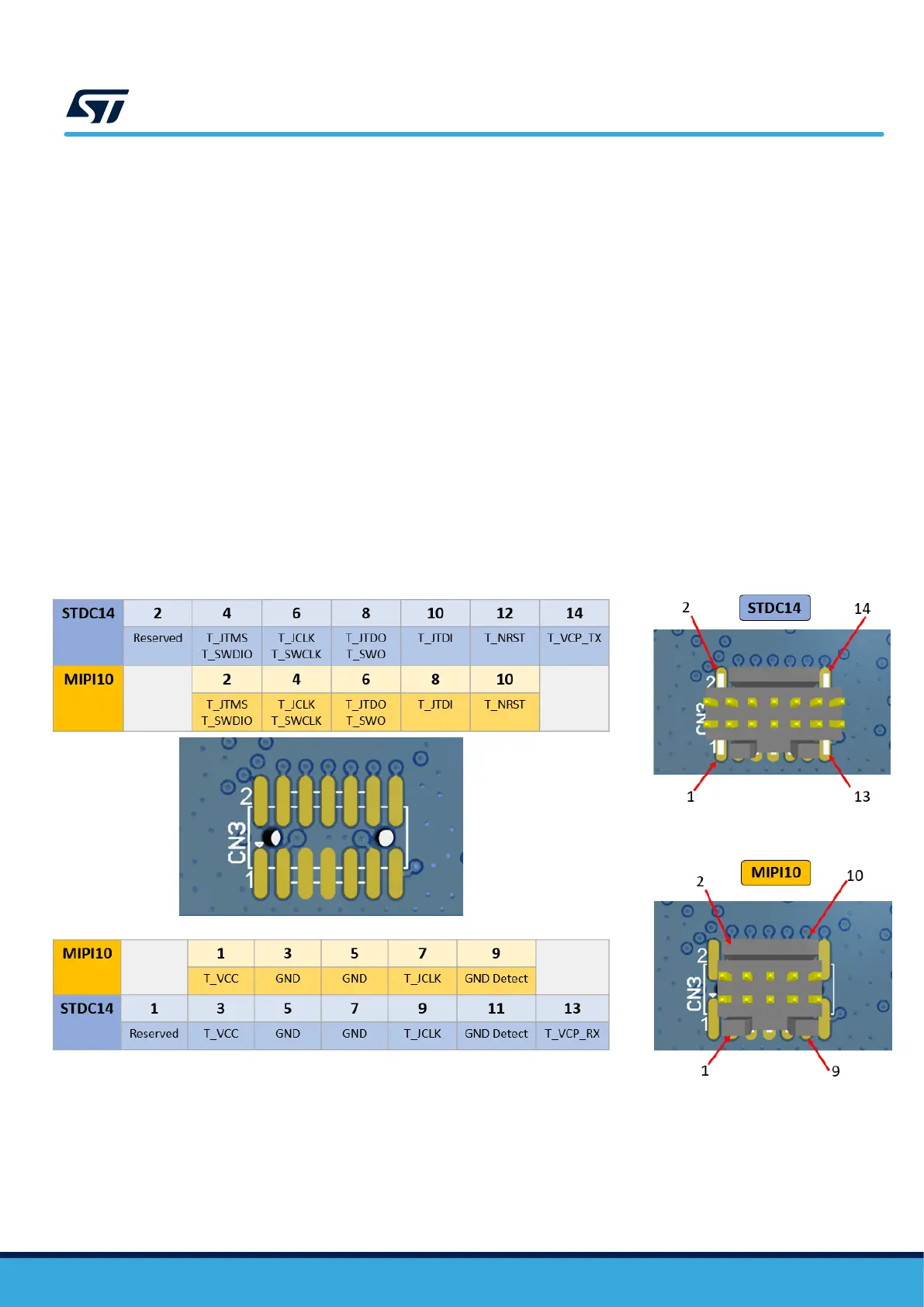
7.12.2 MIPI10/STDC14 pinout
Figure 6 Pinout of the MIPI10/STDC14 connector (CN3 of the MCU RF board)