Hardware layout and configuration UM1974
28/82 DocID028599 Rev 7
ESD protection part ESDA6V1BC6 is implemented on USB port because all USB pins on
STM32 can be used as V
BUS
or GPIO on the STM32 Nucleo-144 board.
Note: If these pins are dedicated to USB port only, the USBLC6-4SC6 protection part is more
suitable to protect USB port. If USB pin ID is not used, USBLC6-2SC6 can be used.
6.11 Ethernet
The STM32 Nucleo-144 board supports 10M/100M Ethernet communication by a PHY
LAN8742A-CZ-TR (U9) and RJ45 connector (CN14). Ethernet PHY is connected to the
STM32 microcontroller via the RMII interface. 50MHz clock for the STM32 microcontroller is
generated by the PHY RMII_REF_CLK.
Note: 1. NUCLEO-F303ZE, NUCLEO-F412ZG, NUCLEO-F413ZH, NUCLEO-F446ZE and
NUCLEO-F722ZE do not support the Ethernet function.
2. JP6 and JP7 must be closed when using Ethernet.
3. Ethernet PHY LAN8742A should be set in power-down mode (in this mode Ethernet PHY
ref clock turns off) to achieve the expected low-power mode current. This is done by
configuring Ethernet PHY LAN8742A Basic Control Register (at address 0x00) Bit 11
(Power Down) to '1'. SB13 can also be removed to get the same effect.
PG7 USB GPIO IN
NUCLEO-F303ZE:
JP4 ON, SB184 ON,
SB185 OFF
JP4 OFF
NUCLEO-F303ZE:
V
BUS
detection
All other Nucleo
boards:
JP4 ON, SB184 OFF
SB185 ON
All other Nucleo boards:
USB overcurrent alarm
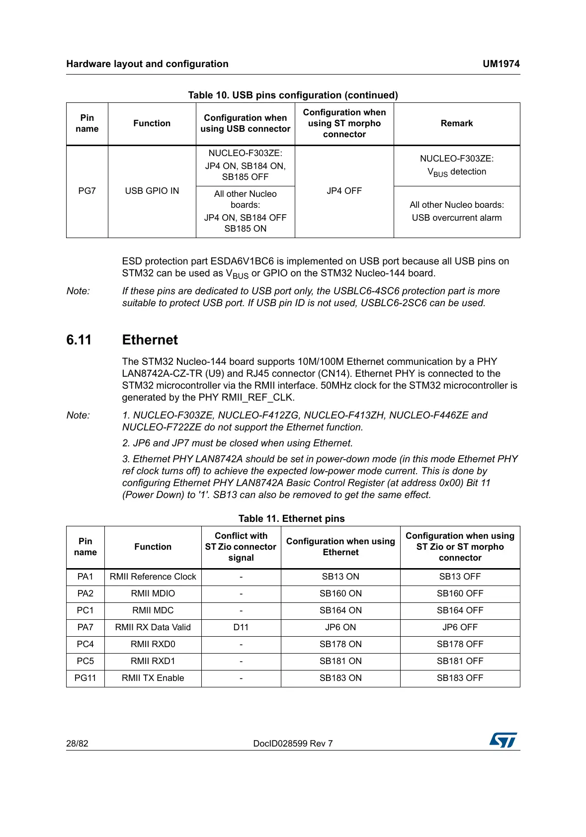
Table 10. USB pins configuration (continued)
Pin
name
Function
Configuration when
using USB connector
Configuration when
using ST morpho
connector
Remark
Table 11. Ethernet pins
Pin
name
Function
Conflict with
ST Zio connector
signal
Configuration when using
Ethernet
Configuration when using
ST Zio or ST morpho
connector
PA1 RMII Reference Clock - SB13 ON SB13 OFF
PA2 RMII MDIO - SB160 ON SB160 OFF
PC1 RMII MDC - SB164 ON SB164 OFF
PA7 RMII RX Data Valid D11 JP6 ON JP6 OFF
PC4 RMII RXD0 - SB178 ON SB178 OFF
PC5 RMII RXD1 - SB181 ON SB181 OFF
PG11 RMII TX Enable - SB183 ON SB183 OFF
 Loading...