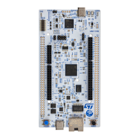
6.3.3 Using an external debug tool to program and debug the on-board STM32
The STM32H7Rx/7Sx Nucleo-144 board supports an external debug tool CN1 for SWD/JTAG and trace
debugging. Keep the embedded STLINK-V3EC running. Power on the STLINK-V3EC at first until the COM LED
turns red. Then connect the external debug tool through the MIPI20 debug connector (CN1).
Table 7 describes the MIPI20 connector (CN1) pinout.
Table 7. MIPI20 debug connector (CN1) pinout
MIPI20 pin
number
Signal name STM32 pin Function
1 VDD - Target VDD
2 MCU.SWDIO PA13
Target SWDIO using SWD protocol or target JTMS (T_JTMS) using
JTAG protocol
4 MCU.SWCLK PA14
Target SWCLK using SWD protocol or target JTCK (T_JTCK) using
JTAG protocol
6 MCU.SWO PB3
Target SWO using SWD protocol or target JTDO (T_JTDO) using JTAG
protocol
7 KEY - NC
8 MCU.JTDI PA15
Not used by SWD protocol, target JTDI (T_JTDI) using JTAG protocol
(SB27 ON, default OFF)
10 NRST NRST Target NRST
12 TRACE_CLK PE2 Trace clock signal
14 TRACE_D0 PE3 Trace data0 signal
16 TRACE_D1 PG14 Trace data1 signal
18 TRACE_D2 PD2 Trace data2 signal
20 TRACE_D3 PC12 Trace data3 signal
3, 5, 9, 11, 13,
15, 17, 19
GND - Ground
UM3276
Hardware layout and configuration
UM3276 - Rev 1
page 13/40

 Loading...