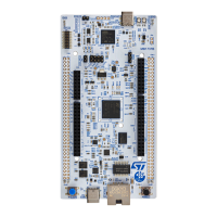
Tricolor PWR status LED (LD9)
The tricolor (green, orange, and red) LED (LD9) provides information about the STLINK-V3EC target power
status.
• LED OFF: The target is not powered by STLINK-V3EC.
• Green: The Nucleo board power request is less or equal to the USB port power capability.
• Orange: The Nucleo board power request is higher than the USB port power capability. It is recommended
to connect to another USB port for full functionality of the board.
• Red: The Nucleo board power has been automatically switched off after the detection of an overcurrent.
Switch to a more powerful USB port, and if the issue persists, investigate what might cause an
overconsumption of the board.
• Red slow blinking: Internal error due to wrong hardware environment. STLINK-V3EC is not functional.
6.6 Push-buttons
Two buttons are available on the Nucleo board.
Reset button (B1)
The black button connected to NRST is used to reset the STM32 microcontroller. When the button is pressed the
logic state is LOW, otherwise, the logic state is HIGH.
User button (B2)
The blue button for the user and wake‑up functions is connected to PC13 to support the wake‑up function of the
STM32 microcontroller. When the button is pressed, the logic state is LOW, otherwise, the logic state is HIGH.
6.7
Oscillator clock sources
Three clock sources are described below:
• LSE is the 32.768 kHz crystal for the STM32 embedded RTC.
• MCO is the 8 MHz clock from STLINK-V3EC for the STM32 microcontroller
• HSE is the 24 MHz oscillator for the STM32 microcontroller.
6.7.1 LSE: OSC 32 KHz clock supply
There are three ways to configure the pins corresponding to the low-speed clock (LSE):
LSE on-board oscillator X2 crystal (default configuration)
Refer to the application note Oscillator design guide for STM8AF/AL/S, STM32 MCUs and MPUs (AN2867), with
the following characteristics: 32.768 kHz, 6 pF, and 20 ppm. It is recommended to use NX2012SA-32.768KHz-
EXS00A-MU00527 manufactured by NDK. The following configuration is needed:
• R42 and R43 ON
Oscillator from external to PC14
From the external oscillator through PC14, Zio connector (CN11) pin 25. The following configuration is needed:
• R42 and R43 OFF
• SB64 ON
LSE not used
PC14 and PC15 are used as GPIOs instead of low‑speed clocks. The following configuration is needed:
• R42 and R43 OFF
• SB64 and SB65 ON
UM3276
Hardware layout and configuration
UM3276 - Rev 1
page 21/40

 Loading...