List of figures
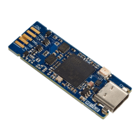
Figure 1. STLINK-V3MINIE top, bottom, and cable views..............................................1
Figure 2. STLINK-V3MINIE hardware board.......................................................6
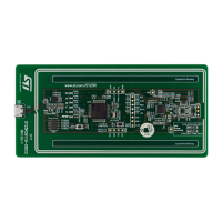
Figure 3. MB1762 top layout .................................................................7
Figure 4. MB1762 bottom layout...............................................................7
Figure 5. MB1762 mechanical drawing (in millimeters) ...............................................8
Figure 6. CN4 STDC14 connector (Top view) ..................................................... 11
UM2910
List of figures
UM2910 - Rev 2
page 19/20
 Loading...