UM2448 Rev 6 25/49
UM2448 Board connectors
48
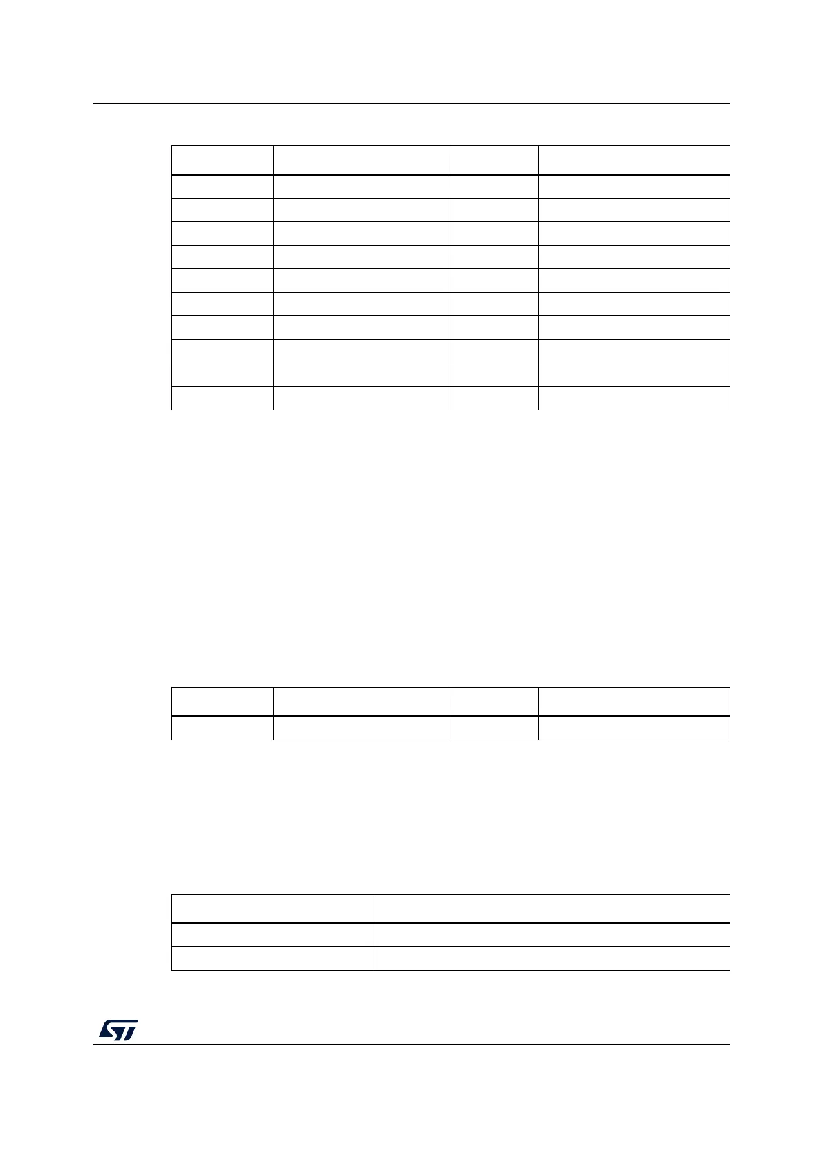
8.2.3 Virtual COM port connector
The CN3 connector allows the connection of a target UART for the Virtual COM port
function. The debug connection (through JTAG/SWD or SWIM) is not required at the same
time. However, a GND connection between STLINK-V3SET and target is required and must
be ensured in some other way in case no debug cable is plugged. The related pinout for the
VCP connector is listed in
Table 8.
8.2.4 SWIM connector
The CN4 connector allows the connection to an STM8 SWIM target. The related pinout for
the SWIM connector is listed in
Table 9.
Table 7. Legacy Arm 20-pin JTAG/SWD IDC connector CN2
Pin number Description Pin number Description
1T_VCC
(1)
1. Input for STLINK-V3SET.
2NC
3NC4GND
(2)
2. At least one of these pins must be connected to the ground on the target side for correct behavior
(connecting all is recommended for noise reduction on the ribbon).
5 T_JTDI/NC
(3)
3. NC means not required for the SWD connection.
6GND
(2)
7 T_JTMS/T_SWDIO 8 GND
(2)
9 T_JCLK/T_SWCLK 10 GND
(2)
11 T_JRCLK
(4)
/NC
(3)
4. Optional loopback of T_JCLK on the target side, required if loopback removed on the STLINK-V3SET side.
12 GND
(2)
13 T_JTDO/T_SWO
(5)
5. SWO is optional, required only for Serial Wire Viewer (SWV) trace.
14 GND
(2)
15 T_NRST 16 GND
(2)
17 NC 18 GND
(2)
19 NC 20 GND
(2)
Table 8. Virtual COM port connector CN3
Pin number Description Pin number Description
1T_VCP_TX
(1)
1. Input for STLINK-V3SET. Must be connected to UART_TX on target.
2T_VCP_RX
(2)
2. Output for STLINK-V3SET. Must be connected to UART_RX on target.
Table 9. SWIM connector CN4
Pin number Description
1T_VCC
(1)
2SWIM_DATA