B-STLINK-ISOL board extension description UM2448
42/49 UM2448 Rev 6
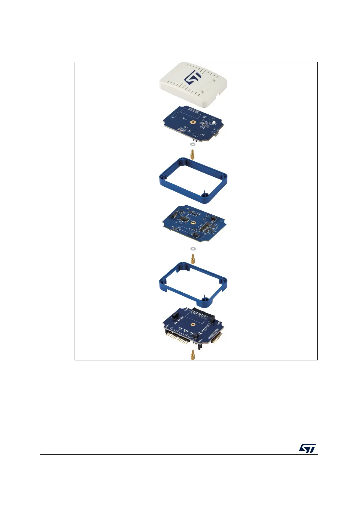
Figure 20. Opened casing for access to all connectors with B-STLINK-ISOL
For connector description, refer to Section 8.2.
13.3 Bridge GPIO direction
On the B-STLINK-ISOL board the direction of bridge GPIO signals are fixed by hardware:
• GPIO0 and GPIO1 are the target input and ST-LINK output.
• GPIO2 and GPIO3 are the target output and ST-LINK input.