B-STLINK-VOLT board extension description UM2448
36/49 UM2448 Rev 6
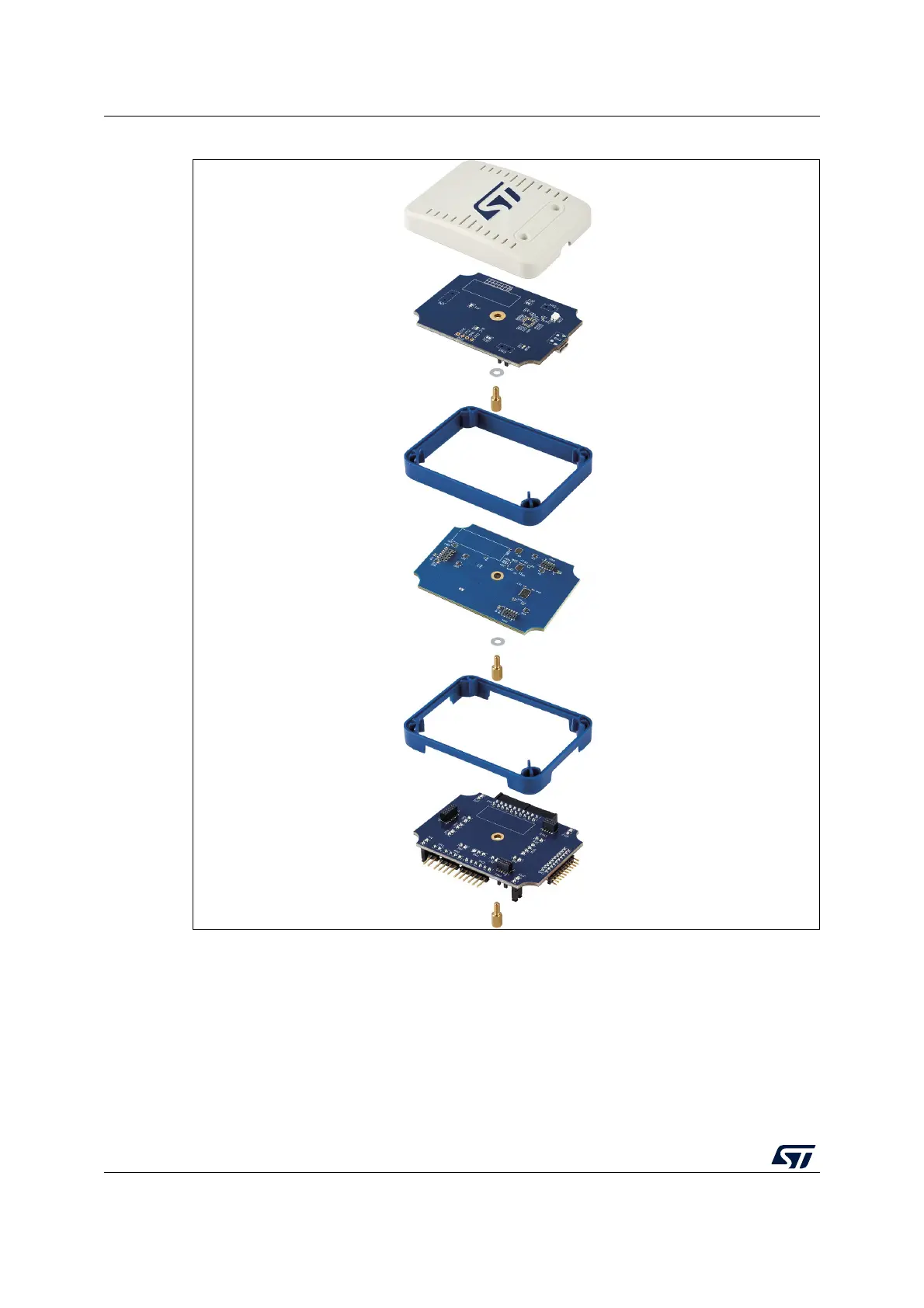
Figure 17. Opened casing for access to all connectors with B-STLINK-VOLT
For connector description, refer to Section 8.2.
12.3 Selection of bridge GPIO direction
The level-shifter components on the B-STLINK-VOLT board require to manually configure
the direction of bridge GPIO signals. This is possible through the SW1 switch on the bottom
of the board. Pin1 of SW1 is for bridge GPIO0, pin4 of SW1 is for bridge GPIO3. By default,
the direction is target output/ST-LINK input (selectors on ON/CTS3 side of SW1). It can be