EasyManuals Logo

ST STM32 NUCLEO-F411RE User Manual

ST STM32 NUCLEO-F411RE
68 pages
To Next Page IconTo Next Page
To Previous Page IconTo Previous Page
Page #12 background image
Hardware layout and configuration UM1724
12/68 UM1724 Rev 14
6 Hardware layout and configuration
The STM32 Nucleo board is designed around the STM32 microcontrollers in a 64-pin LQFP
package.
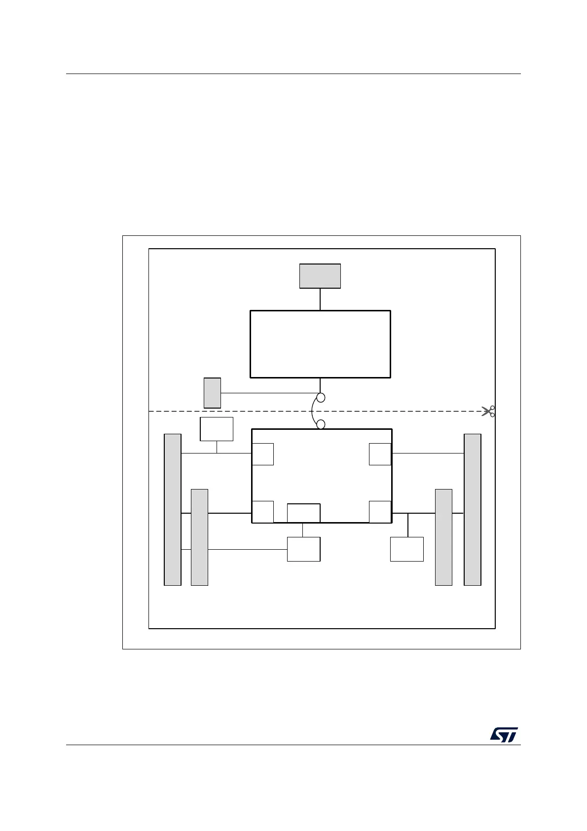
Figure 2 shows the connections between the STM32 and its peripherals (ST-LINK/V2-1,
push-button, LED, ARDUINO
®
connectors, and ST morpho connector).
Figure 3 and Figure 4 show the location of these features on the STM32 Nucleo board.
Figure 5 shows the mechanical dimension of the STM32 Nucleo board.
Figure 2. Hardware block diagram
RESET
Mini
USB
IO
IO IO
IO
ST-LINK part
Embedded
ST-LINK/V2-1
STM32
Microcontroller
B1
USER
B2
RESET
LED
LD4
MCU part
SWD
ST morpho extension header
ARDUINO
®
connector
ARDUINO
®
connector
ST morpho extension header
MS34374V2

Table of Contents

Questions and Answers:

Question and Answer IconNeed help?

Do you have a question about the ST STM32 NUCLEO-F411RE and is the answer not in the manual?

ST STM32 NUCLEO-F411RE Specifications

General IconGeneral
MicrocontrollerSTM32F411RET6
CoreARM Cortex-M4
Operating Voltage3.3V
Input Voltage7V to 12V
Operating Frequency100 MHz
Flash Memory512 KB
SRAM128 KB
Digital I/O Pins50
Analog Input Channels16
DAC Channels1
On-board DebuggingST-LINK/V2-1
Communication InterfacesI2C, SPI, USART
USBUSB 2.0
ConnectorsArduino Uno
Form FactorNucleo

Related product manuals