Do you have a question about the ST STM32F401 and is the answer not in the manual?
Introduces the STM32F401 Discovery kit for evaluating and developing STM32F4 applications.
Explains conventions for jumpers, solder bridges, and other symbols used in the manual.
Step-by-step guide to configure and launch the DISCOVER application on the STM32F401 board.
Lists necessary PC, OS, and USB cable requirements for using the STM32F401 Discovery kit.
Identifies compatible IDEs and toolchains for developing applications with the STM32F401 Discovery kit.
Provides the official order code for purchasing the STM32F401 Discovery kit.
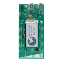
Details the core features and benefits of the STM32F401 Discovery board, including MCU, sensors, and connectivity.
Details the STM32F401VCT6 microcontroller's specifications, performance, and power efficiency benefits.
Explains the integrated ST-LINK/V2 for programming and debugging the STM32F401 on-board.
Instructions for utilizing the onboard ST-LINK/V2 to program the STM32F401 microcontroller.
Guide for using the board's ST-LINK/V2 to program an external STM32 application board via CN2.
Describes how the board receives power and the available selection options for power sources.
Details the function and location of all LEDs on the STM32F401 Discovery board.
Explains the function of the user (B1) and reset (B2) pushbuttons on the board.
Describes the audio DAC, MEMS microphone, and audio output capabilities of the board.
Details the USB OTG full speed functionality and its associated status LEDs (LD7, LD8).
Describes the E-compass MEMS sensor (LSM303DLHC) and its 3D acceleration/magnetic measurement capabilities.
Describes the Gyroscope MEMS sensor (L3GD20) and its three-axis angular rate measurement capabilities.
Explains the JP2 jumper's role in measuring the STM32F401VCT6's current consumption.
Details configurations for various oscillator clock supply sources and the 32 KHz clock.
Describes the function and states of various solder bridges for board configuration.
Details the male headers P1 and P2 for connecting to external prototyping boards and probing.
Provides a detailed mechanical drawing of the STM32F401 Discovery board with key dimensions and component placement.
Presents the main electrical schematic diagram for the STM32F401 Discovery board.
Electrical schematic detailing the ST-LINK/V2 programming and debugging interface.
Schematic diagram showing the connections and configuration of the STM32F401VCT6 microcontroller.
Electrical schematic for the board's audio DAC, MEMS microphone, and audio output components.
Electrical schematic detailing the USB OTG Full Speed interface and associated components.
Electrical schematics for the board's MEMS sensors, pushbuttons, and LEDs.
Records the revision history and changes made to this document over its lifecycle.
| Series | STM32F4 |
|---|---|
| Core | ARM Cortex-M4 |
| Clock Speed | 84 MHz |
| Communication Interfaces | I2C, SPI, USART, USB |
| Operating Voltage | 1.7 V to 3.6 V |
| Number of I2Cs | 3 |
| Number of SPIs | 3 |
| Number of USARTs | 3 |
| ADC | 12-bit |
| DAC | 12-bit |
| Timers | Advanced-control timers |
| Operating Temperature Range | -40°C to 85°C |
| Package | LQFP64, LQFP48 |


 Loading...