DocID029937 Rev 2 17/22
AN4943 New DMA2D features to support Intel 8080 displays
21
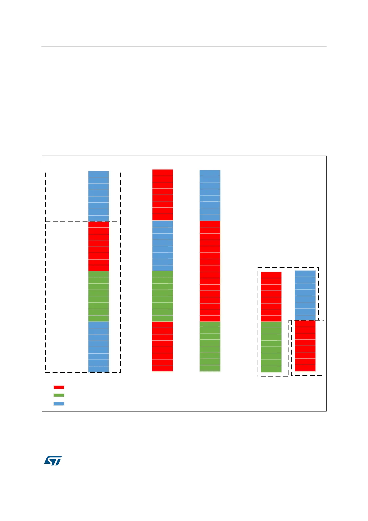
5.3 DMA2D reordering use case examples
5.3.1 24bpp/18bpp over 16-bit FSMC data bus interface
In order to support 24bpp displays using the 8080 standard, two operations are required on
the frame buffer data:
• Red and blue swap
• MSB and LSB bytes of a half-word swap
Figure 8 shows the operations performed by the DMA2D allowing to have the good byte
order corresponding to the Intel 8080 protocol for 24bpp color depth over a 16-bit interface.
Figure 8. DMA2D operations to support 24bpp over 16-bit interface
Note: On MCUs not supporting the byte swap, a hardware fix can be implemented by swapping
the data lines of the LCD interface on the board. The display D[15:8] lines are connected to
the FSMC D[7:0] lines and the display D[7:0] lines are connected to the FSMC D[15:8] lines.
MSv48350V1
B0 [7]
B0 [6]
B0 [5]
B0 [4]
B0 [3]
B0 [2]
B0 [1]
B0 [0]
G0 [7]
G0 [6]
G0 [5]
G0 [4]
G0 [3]
G0 [2]
G0 [1]
G0 [0]
R0 [7]
R0 [6]
R0 [5]
R0 [4]
R0 [3]
R0 [2]
R0 [1]
R0 [0]
@+0
@+1
@+2
B1 [7]
B1 [6]
B1 [5]
B1 [4]
B1 [3]
B1 [2]
B1 [1]
B1 [0]
@+3
Memory
16-bit FSMC data bus
Pixel 0
Pixel 1
B0 [7]
B0 [6]
B0 [5]
B0 [4]
B0 [3]
B0 [2]
B0 [1]
B0 [0]
G0 [7]
G0 [6]
G0 [5]
G0 [4]
G0 [3]
G0 [2]
G0 [1]
G0 [0]
R0 [7]
R0 [6]
R0 [5]
R0 [4]
R0 [3]
R0 [2]
R0 [1]
R0 [0]
D15
D14
D13
D12
D11
D10
D9
D8
D7
D6
D5
D4
D3
D2
D1
D0
B0 [7]
B0 [6]
B0 [5]
B0 [4]
B0 [3]
B0 [2]
B0 [1]
B0 [0]
G0 [7]
G0 [6]
G0 [5]
G0 [4]
G0 [3]
G0 [2]
G0 [1]
G0 [0]
R0 [7]
R0 [6]
R0 [5]
R0 [4]
R0 [3]
R0 [2]
R0 [1]
R0 [0]
R1 [7]
R1 [6]
R1 [5]
R1 [4]
R1 [3]
R1 [2]
R1 [1]
R1 [0]
Red blue swap
R1 [7]
R1 [6]
R1 [5]
R1 [4]
R1 [3]
R1 [2]
R1 [1]
R1 [0]
Byte swap
@+0
@+1
@+2
@+3
G0 [7]
G0 [6]
G0 [5]
G0 [4]
G0 [3]
G0 [2]
G0 [1]
G0 [0]
R0 [7]
R0 [6]
R0 [5]
R0 [4]
R0 [3]
R0 [2]
R0 [1]
R0 [0]
R1 [7]
R1 [6]
R1 [5]
R1 [4]
R1 [3]
R1 [2]
R1 [1]
R1 [0]
B0 [7]
B0 [6]
B0 [5]
B0 [4]
B0 [3]
B0 [2]
B0 [1]
B0 [0]
12
Transfer
number
Pixel 0
@+0
@+1
@+2
@+3
Pixel 1
Green component
Red component
Blue component

 Loading...


