UM2243 Rev 2 13/41
UM2243 Supplying power to the X-NUCLEO-LPM01A
40
7 Supplying power to the X-NUCLEO-LPM01A
The X-NUCLEO-LPM01A board is designed to be powered from one of the three following
power sources:
• USB FS micro-B connector (either USB h
ost port or USB charger) via CN5
• External DC power supply via CN7
• Arduino Uno (CN4) connector or Arduino Nano (CN13) connector via the 5V pin
See Figure 2: Hardware block diagram for details regarding the power tree, and
Figure 3: X-NUCLEO-LPM01A layout top view for connector locations.
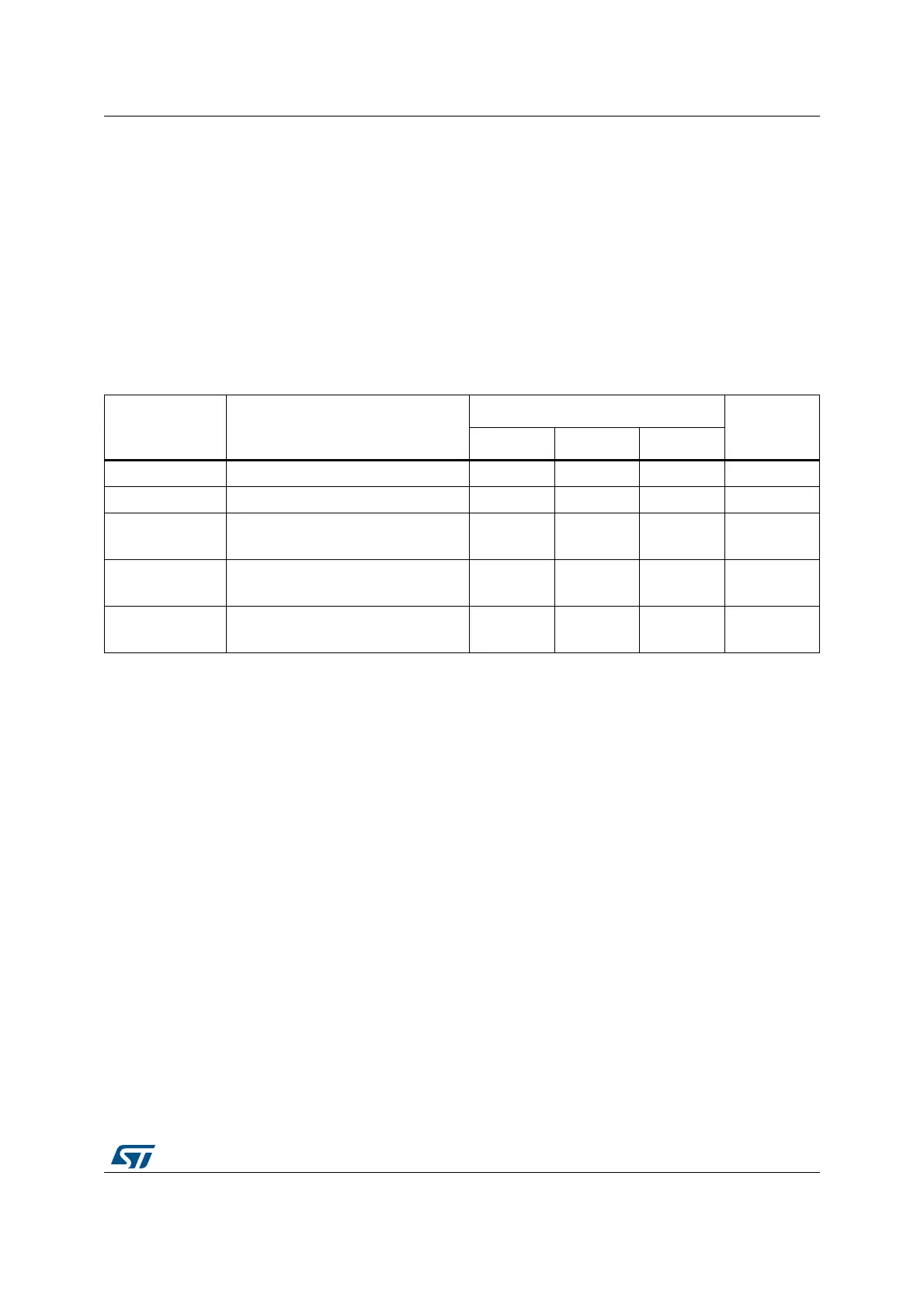
Table 2. Power input source setting summary
Power source
from
Power connection
JP3 setting
JP2
setting
ARD USB Ext
USB host CN5: USB Type micro-B connector open closed open open
USB charger CN5: USB Type micro-B connector open closed open closed
Ext power supply
CN7: 7 V to 10 V DC pin +
CN7: GND pin -
open open closed open
Arduino Uno
conn
ectors
CN4: pin 5V
CN4: pin GND
closed open open open
Arduino Nano
conn
ectors
CN13: pin +5V
CN13: pin GND
closed open open open
Note: Regardless of the power supply input source, the X-NUCLEO-LPM01A board must be
powered by a power supply unit or by an auxiliary equipment complying with the standard
EN-60950-1: 2006+A11/2009, and must be Safety Extra Low Voltage (SELV) with limited
power capability.
7.1 Power source from an USB host port (default setting)
A jumper should be inserted in the ‘USB’ position of JP3 as shown in Figure 5: JP3 (USB
setting). No jumper should be
inserted in JP2.
A USB Type-A to USB Type micro-B cable is
required to supply the X-NUCLEO-LPM01A
board (CN5: USB FS micro-B connector) to a PC host USB port.
When the USB cable is connected, 5 V DC is provided by VBUS from the USB host port of
the
PC. At this step, only the embedded MCU of X-NUCLEO-LPM01A is supplied. A USB
enumeration is performed between the embedded MCU and the host PC to negotiate
500 mA on VBUS. If USB enumeration succeeds, X-NUCLEO-LPM01A peripherals
are
supplied and the target board supply can be enabled. Otherwise (if USB enumeration fails),
the X-NUCLEO-LPM01A peripherals are not supplied, the red LED (LD2) is turned ON and
a message is displayed on the LCD display.
If an abnormal current higher than 600 mA is drawn from the USB connector (CN5) by the
X-
NUCLEO-LPM01A, an embedded current protection clamps the current and LED LD5

 Loading...

