Power supply connections of a target board UM2243
22/41 UM2243 Rev 2
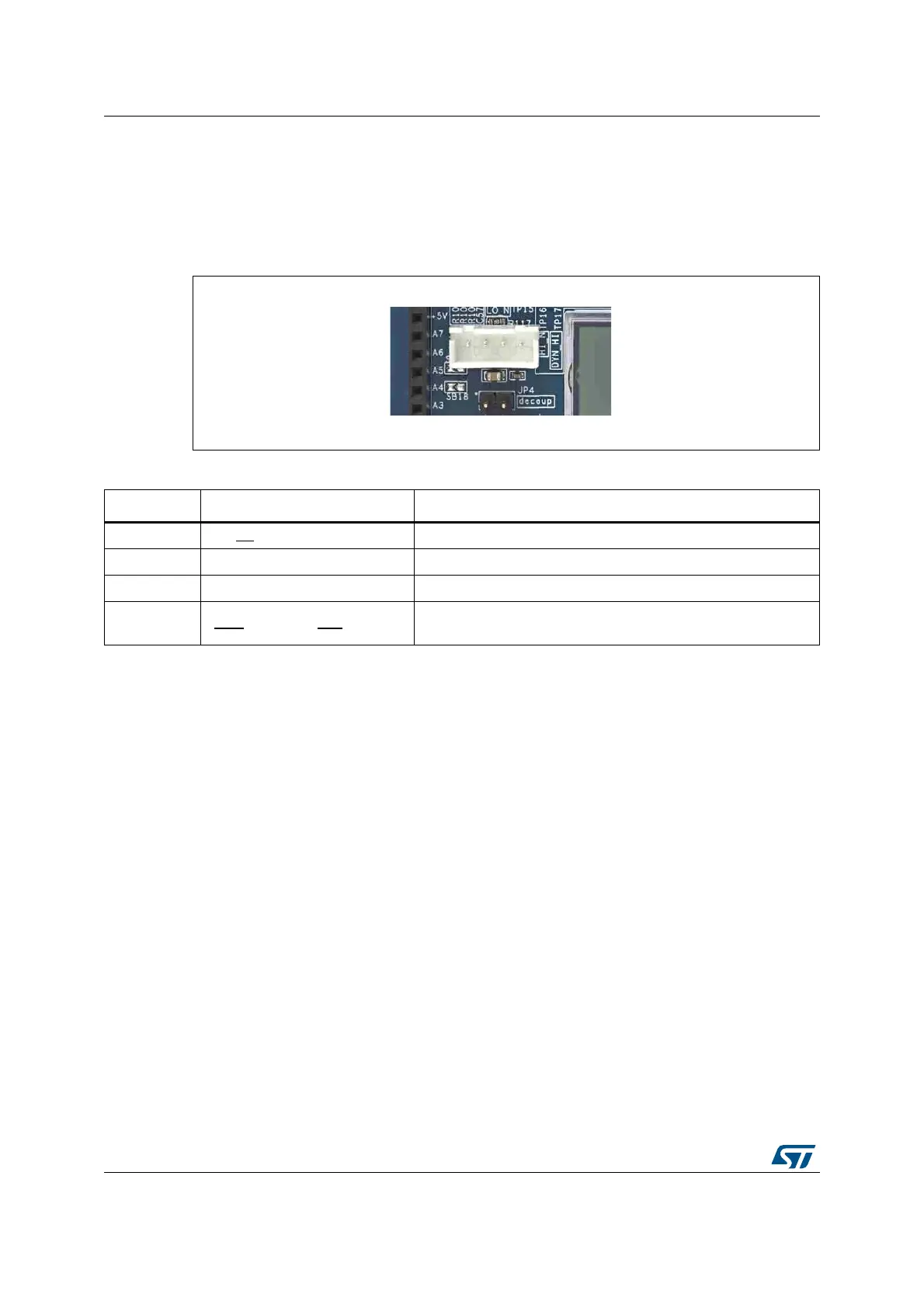
8.3 Power supply connections of a target board with basic
connector CN14
CN14 is a common XH series 4-pin connector with a 2.54 mm pitch. It can be used to supply
and measure the target board consumption using a wire connection.
Figure 15. Basic connector CN14
Table 4. Pin description of the basic connector CN14
CN14 pin Signal Usage
Pin 1 GND
(-) Ground of the target
Pin 2 VDD Alternate power supply source (not measured)
Pin 3 VOUT (+) Positive connection of the target, current is measured
Pin 4 V
OUT_MONITORING
Mirror of VOUT. Allows VOUT monitoring without impacting
curre
nt/power measurements
The target board should be supplied through GND (pin1) and VOUT (pin3) of CN14.
VOUT_MONITORING (pin4) is a buffered copy of the output voltage VOUT. It can be used
to monitor
VOUT with a voltmeter or oscilloscope without impacting the current/power
measurements.
Alternatively, VOUT_MONITORING can be used a
s a reference with a voltage divider to
generate a bias voltage without impacting the current consumption.
Note: VOUT_MONITORING output has 150 ohms seria
l resistance to protect it output buffer.
VDD (pin2) can be used as an alternate power source to supply some peripherals of the
t
arget board. The VDD voltage is equal to VOUT (with no load on VOUT). VDD is slightly
higher (30 mV maximum in dynamic mode and 60 mV maximum in static mode) than VOUT
whe
n VOUT is fully loaded. The VDD output current should not exceed 500 mA.
Caution: When the X-NUCLEO-LPM01A is
supplied from a PC (USB host port), and VDD supplies
the target board peripherals, do not exceed the 500 mA total budget allowed by the USB
po
rt.
See also Figure 2: Hardware block diagram for further details.

 Loading...

