3 General description, function
10 10.20133
BA_SLE22_EN.DOCX
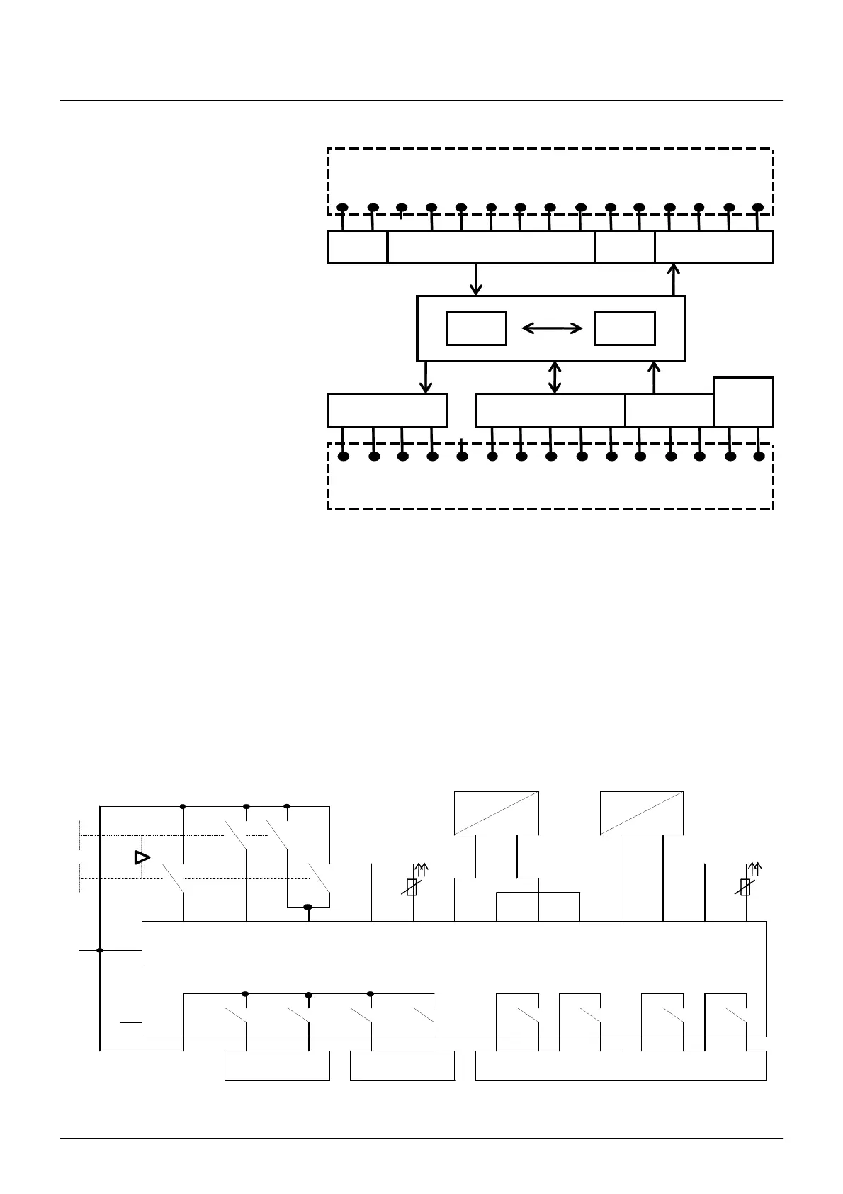
3.4 Block circuit diagram of SLE22
Supply
1: Supply voltage L
Relay outputs Activation
Signal relay
µP1 µP2
ϑ2
ϑ2ϑ2
ϑ2
Supply
Temp relay
ϑ1
ϑ1ϑ1
ϑ1
Analog safety inputs
Load1
19: 15V supply for load sensor 1 UBS
20: Ground for 15V and 24V supply GD
21, 22: Load sensor input 1 I1+/I1-
Load2
23: Load sensor input 2 I2+
24: 24V supply for load sensor 2 UB
Activation
Relay outputs
6: Switching voltage of relays L↑↓
Temp relays
Relay outputs for cutting
motors at overtemperature right/left
ϑ
ϑϑ
ϑ1
16, 17: PTC thermistor input hoist motor
ϑ
ϑϑ
ϑ1
ϑ
ϑϑ
ϑ2
25, 26: PTC thermistor input travel motor
ϑ
ϑϑ
ϑ2
Signal relays
27, 28: Signal relay err
29, 30: Signal relay option
3.5 Simplified circuit diagram
S211
S212
3 4 5 16 17 19 20 21 22 23 24 25 26
S
↑
S
↓
S
↕↕
UBS GD I1+ I1- I2+ UB
1 L
err option
2 N
L
↓↑
K
↑
K
K
↓
K
6 7 8 9 10 27 28 29 30 12 13 14 15
Power section signal
Power section travel
ϑ1
ϑ1ϑ1
ϑ1 ϑ2
ϑ2ϑ2
ϑ2
left
Fast downFast up
Up
Power section downPower section up
Temp relay
Down
right
Signal relay
ϑ
ϑϑ
ϑϑ
ϑϑ
ϑ