4 Installation
10.2013 17
BA_SLE22_EN.DOCX
4 Installation
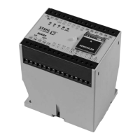
4.1 Dimensions
100 x 110 x 75 mm (B x H x T)
4.2 Mounting
Clipped onto 35 mm top hat rail 3 (EN 50022-35)
• Screwed onto base of casing (M4) with pull-out slide
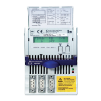
4.3 Lead connection
30 box terminals with captive plus-minus screws
• Per box terminal: 1 x 4 mm2 solid or 1 x 2.5 mm2 stranded wire with sleeve
DIN 46 228 or 2 x 1.5 mm2 stranded wire with sleeve DIN 46228
Installation must be performed by a skilled electrician. The maximum values for tighten-
ing torques given in EN ISO 898-1 must be observed for all screws.
All screws must be checked for firmness and tightened if necessary at every mainten-
ance, at least once a year.
4.4 Replacement of device or sensor
DANGER
After a device or load sensor has been replaced by a
commissioning test (see chapter 5: Commissioning and testing) must be repeated and the
reading of the operating hours counter of the device which has been replaced recorded in
the crane logbook.
4.5 Installation
Installation in a panel box, IP 54 minimum