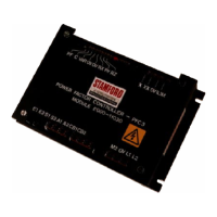
3.3.3 AVR Control Output ( A1 , A2 )
These are connected directly to the corresponding terminals on
the AVR. Should the cable length between the PFC3 and the
AVR exceed 5m (16ft) then it is advisable to use screened leads
with the cable screen connected to terminal A1.
Important ! Do NOT ground the screen at either end.
3.3.4 Circuit Breaker Input ( CB1 , CB2 )
Contact closure of these terminals switches the PFC3 into power
factor (or VAr) control operation. These two terminals would
normally be connected to a normally open auxiliary contact on the
generator circuit breaker.
In the case of multi-generator installations, where the generator
can run off-grid in parallel (island system), then a normally open
auxiliary contact from the incoming mains circuit
breaker/contactor MUST be connected in series with the 'E2'
supply to the PFC. The voltage matching facility will then NOT
operate in island operation. (See Fig 9).
Where the PFC3 is used to replace an earlier VAr-2 then the
alternative wiring as shown in Fig 7 can be used. This will
eliminate the need for any wiring changes when fitting the new
PFC3. 'Voltage matching' will NOT operate with this wiring
configuration.
3.4 Installing Options - Fig 8
If it is required to expand on the basic use of the PFC3 and to use
one or more of the built-in options then the following notes apply.
Note: The numbers in the <brackets> refer to the relevant feature
shown in Fig 8.
3.4.1 Remote Power Factor (VAr) Adjustment - <1>
Should front panel/remote adjustment of power factor or VAr be
required then a 10k ohm / 1W potentiometer may be connected to
terminals RX, RY and RZ as shown. The use of screened leads is
essential with the screen connected to the adjacent '0V' terminal.
Important ! Do NOT ground the screen at the potentiometer
end. Simply leave the screen unconnected and
insulated.
When fitted, the external potentiometer has complete control over
the PFC3 set-point and the on-board adjustment is no longer
effective.
3.4.2 Remote Switching of Power Factor/Var
Mode - <2>
Should front panel/remote selection of power factor or Var
operating modes be required then a single pole changeover
switch (rated at 1A/240V) may be connected to the terminals PF ,
C and VAR as shown. This will replace the link which is normally
fitted. The use of screened leads is essential with the screen
connected to the adjacent '0V' terminal.
Important ! Do NOT ground the screen at the switch end.
Simply leave the screen unconnected and
insulated.
3.4.3 Generator Current Limiting - <3>
Under certain operating conditions it is desirable to be able to
limit the maximum current delivered by the generator. Connect
the current transformer to the terminals 0V and ILIM as shown.
The current transformer should have a secondary current output
of 0.32A (class index 3.0) at 100% generator output and must be
positioned in the correct phase and with the correct polarity for
the successful operation of the PFC3. See loose leaf wiring
diagrams for details of your particular machine. Bar mounted
current transformers with the correct secondary rating and
mechanical fixings are available from Newage International.
Important ! Do NOT ground either lead S1 or S2 of the
current limiting C/T circuit.
3.4.4 Excitation Voltage Limiting - <4>
Under certain operating conditions it is desirable to be able to
limit the minimum excitation voltage (and therefore excitation
current) to prevent generator pole slipping. All that is required to
enable this facility is to install two wires from X and XX (exciter
field + and -) on the generator to the terminals X and XX on the
PFC3. See loose leaf wiring diagrams for any additional details of
your particular machine.
Important ! Do NOT ground either lead X or XX.
3.4.5
Voltage Matching - <5>
Under certain operating conditions it is desirable to use the
voltage matching facility built into the PFC3. The inputs L1 and L2
have been designed to accept a standardised 110-120Vac supply
from the customers low, medium or high voltage bus. In ALL
cases the supply to the PFC3 MUST be isolated using a suitable
transformer but unlike the other unit inputs, the phasing is
unimportant. The input burden is typically 5VA.
Important ! Do NOT ground either lead L1 or L2.
3.5 PFC3 used for Power Factor Correction - Fig 9
It may be a requirement of certain applications to use the installed
generating capacity in conjunction with the PFC3 to 'correct the
power factor' of the incoming mains supply (at the consumers
incoming tie with the mains). In all cases it is necessary to protect
the generator against excessive current demand by fitting the
current limiting option.
The current limiting transformer(0.32A sec) MUST be fitted in the
generator output (as shown in Fig 9) and must be correctly
phased.
The power factor control current transformer (5A sec) MUST be
fitted in the incoming mains tie with the correct position and
phasing. This is usually 'U' phase but local variations may be 'A'
phase, L1 or cables 'red' in colour.
IF IN DOUBT - REFER TO FACTORY


 To Next Page