PFC3 controls PF/VAR - Midway ( 50% )
ILIM - Fully CCW ( 0% )
GAIN - Fully CCW
BAND - Fully CCW
XLIM - Fully CCW
Isolate voltage matching transformer if fitted.
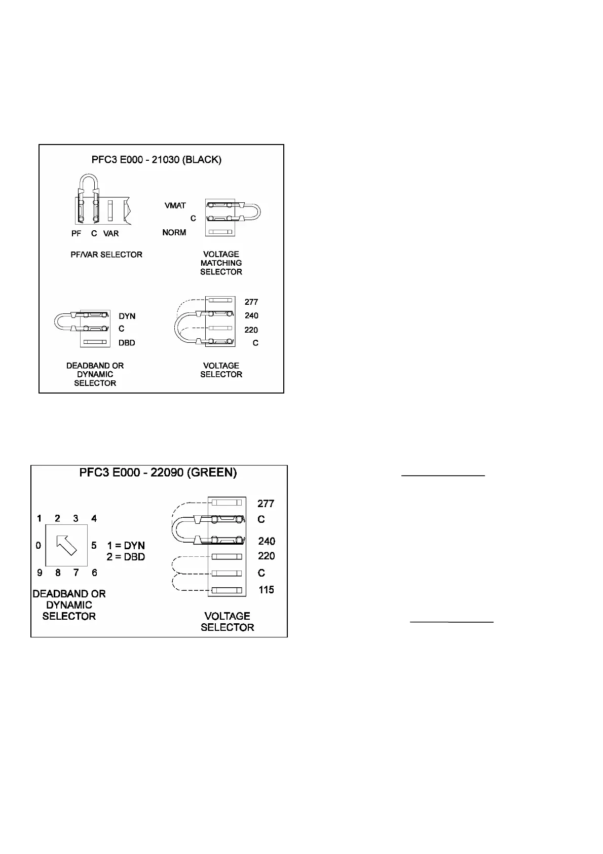
The Input Voltage Selection should be made appropriate for the
application (normally line-neutral voltage). Refer to wiring
diagrams supplied with your machine for further details.
4.2.2 Droop Setting
• Having checked that the generator is safe to run, the set
should be started and run up to nominal speed and the AVR
volts control adjusted to give an output voltage equal to that
of the installation mains.
• Paralleling of the generator should now be carried out in
accordance with the set/installation designers instructions. At
this stage the commissioning engineer should take particular
notice of the generator output current.
• If the generator current rises to an abnormally high level then
the generator circuit-breaker should be opened immediately
and the set stopped. In this event it is more than likely that
the droop C/T or its wiring is reversed. If this is the case then
the droop C/T connections to the AVR should be reversed
and the start-up and initial paralleling procedure repeated.
Do not confuse the AVR droop connections S1/S2 with the
PFC3 current transformer connections S1/S2.
• After successful paralleling has been achieved, load should
be applied and increased to approximately 50%. At this point
the power factor should still be near unity. The voltage
across terminals S1 and S2 on the AVR should now be
measured (0.5 to 2.5Vac) and recorded for future reference.
The generator output current should be stable with only
minor variations reflecting small changes in the system
(mains) voltage.
• The droop circuit polarity has now been verified and must
now be set to a level for the best operation of the PFC3.
• Open the generator circuit breaker and stop the set before
proceeding.
The optimum position of the droop control can now be found by
using the following formula:
Potentiometer 0% = Fully Anti-Clockwise
Position 100% = Fully Clockwise
d = 0.25 for SX440 and MX341 AVRs
d = 1.00 for MX321 and SX421 AVRs
e.g If the measured voltage across S1 and S2 on the SX440 AVR
at half-load was 0.5V, then:
The AVR Droop potentiometer should therefore be set to the
midway position.
If the result of this calculation is greater than 100% then it
suggests that the droop C/T ratio is incorrectly rated (or fitted)
and the correct device should be obtained before proceeding
further.
The Droop equipment is now set.
Potentiometer
Position
(%) = X 100%
d
AVR S1 S2 voltage
Potentiometer
Position
(%) = X 100% = 50%
0.25
0.5


 To Next Page