SECTION 4
COMMISSIONING AND ADJUSTMENTS
THERE ARE TWO VERSIONS OF PFC3
PFC3 E000-21030 has BLACK encapsulation
PFC3 E000-22090 is a GREEN board with clear encapsulation
Differences in features and commissioning are referred to where appropriate
To prevent personal injury or damage to
equipment, only qualified personnel should
install or operate this unit. During
commissioning the engineer will have access
to live components and terminals. Maximum
care should be taken when making
adjustments not to contact live parts. Refer to
the generator and switch-gear manufacturers
handbooks for other safety notices.
The following commissioning procedures
cover ONLY the features of the PFC3. They
DO NOT cover such matters as electrical
installation, phase sequence, switchgear or
engine controls.
Important ! The use of Megger or High Potential test
equipment may result in damage to this unit.
Disconnect all leads before using such
equipment.
4.1 Installations
ALL Installations:
- Follow section titled:
4.2 Commissioning Basic System
Installations making use of one or more of the optional
features:
Follow sections titled:
4.2 Commissioning Basic System and:
4.3 Commissioning Options
Installations configured for power factor correction:
Follow sections titled:
4.2 Commissioning Basic System and:
4.4 Power Factor Correction
4.2 Commissioning Basic System
The design of installations involving the paralleling of private
generators with the mains supply will be regulated by the local
generating authority. It is the responsibility of the commissioning
engineer to ensure that the necessary approval has been granted
before any paralleling operations are carried out.
The commissioning engineer should also be satisfied that all
system protection equipment is correctly installed, adjusted and
working and that ALL 'site' safety procedures have been
observed.
Before running the generator, the installing/ commissioning
engineer should ensure that all equipment is correctly installed
and that the generator set is safe to start. They should also have
studied the section on user adjustable controls and selection links
and should have become familiar with their function. If the
generator set controls are normally set to apply load automatically
then this feature should be inhibited or switched to 'manual'.
Important ! All paralleling operations must be carried out in
compliance with the generator set designers/
installers instructions. Newage International
take no responsibility for equipment damage
caused by incorrect paralleling operations.
Important ! During commissioning of the PFC3 any
connections to terminals RX, RY and RZ must
be removed.
Commissioning of the basic system is best carried out in three
parts:
1. Preliminary Adjustments.
2. Checking the Droop C/T polarity and setting.
3. Checking of the PFC3 C/T polarity and setting.
4.2.1 Preliminary Adjustments
Before starting the generator set the commissioning engineer
should first make sure that the user adjustable controls and
selection links on the PFC3 and certain AVR controls are set as
follows.
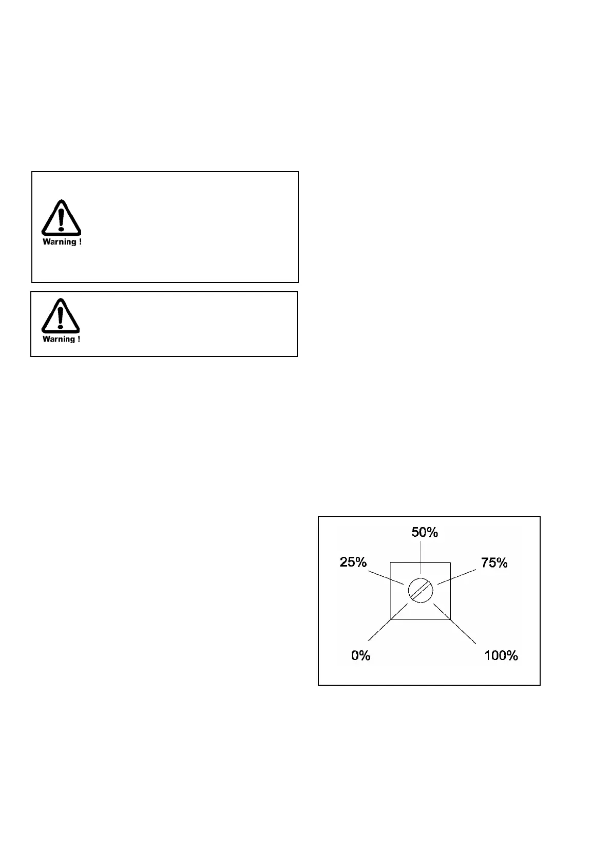
Note: CW = Clockwise Adjustment
CCW = Counter-Clockwise Adjustment
Scaling as shown below
AVR controls Droop - Fully CW ( 100% )
Trim - Fully CCW ( 0% )

 Loading...