4.3.2 Current Limiting Option
Current limiting should only be used when the PFC3 is connected
for Power Factor correction of the incoming main feeder.
If the generator has the MX321 AVR and separate current limiting
equipment fitted, this should be disabled by turning the ILIM
control on the AVR fully CLOCKWISE.
The Current Limiting Transformer should be connected as shown
in Fig 8 (feature 3). The phasing of this C/T is important.
For power factor correction applications it is usual to have two
current transformers (C/T's) fitted in the generator terminal box,
one with a 5 Amp secondary and one with a 330 mA secondary.
There will also be a 5 Amp secondary CT fitted to the Mains
Utility incoming feeder.
The 5 Amp Generator mounted CT is used for normal
Commissioning and Generator Power Factor Control. This will be
unused in Power Factor Correction operation and provision
should be made for connection of a shorting link to prevent an
open CT secondary.
The 330mA Generator mounted CT is used for measuring
generator reactive current for the I Limit feature.
The 5 Amp CT connected to the Mains Utility incoming feeder is
the one used in service for Power Factor correction. This CT
could be carrying site current and provision should be made for
the connection of a shorting link to prevent an open CT
secondary.
1. With the generator stationary connect the generator mounted
5 Amp CT to the PFC3 S1 S2 terminals, observing polarity.
Generator wiring diagrams will show the full details.
2. Connect the Generator mounted 330mA I Limit CT to the
PFC3 connections 0V / ILIM, S1 to ILIM, S2 to 0V. Generator
wiring diagrams will show the full details.
3. Turn the PFC ILIM potentiometer fully anti-clockwise.
4. Set PF / VAR selector to PF.
5. Parallel generator to mains network and run at maximum kW
set-point rating.
6. Adjust the PFC3 to give a generator PF of 0.9 lagging.
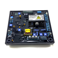
7. Calculate the operating Per Unit Reactive Current (PURC)
against generator rating :-
8. Measure TP2 voltage between 0V and TP2, meter neg (-) on
OV. This should be between +2 and +4V dc. For the location
of TP2, see the label drawing on the PFC3 access cover
plate or PFC3 manual.
9. Calculate required setting of TP2 voltage :-
[ (1 - PURC)
X (TP2 voltage + 0.3) ] - 0.3
10. Turn ILIM slowly clockwise. TP2 voltage should reduce in
value. If it rises then stop generator and reverse the S1 S2
connections to the PFC3 0V and ILIM terminals. Retest from
line 5.
11. Adjust ILIM until TP2 = Required voltage as calculated in line
9.
12. Stop the generator and remove the generator CT
connections S1 S2 on the PFC3 and terminate the generator
CT wires with a suitable shorting link.
13. Connect the mains feeder CT S1 / S2 cables to the PFC3
(observing polarity) and remove the mains feeder CT
shorting link.
14. Turn the PFC3 PF / VAR setting potentiometer to the centre
position.
15. Start the generator and parallel to the mains network.
16. Set the generator to the required operating kW.
17. Adjust the desired mains power factor using the PF /VAR
setting potentiometer on the PFC3.
18. Set-up is now complete.
4.3.3 Low Excitation Limiting Option
Low Excitation Limiting should only be used when the generator
is to be operated at leading power factor.
The Excitation Limiting input (X and XX) should be connected in
parallel with the generator exciter field winding as shown, in Fig 8
(feature 4). The two exciter field connections (X and XX) will
normally be found at the auxiliary terminal block within the
generator. If these terminals do not exist, a suitable connection
block can be obtained from Newage International.
Connect a digital multimeter as follows:
Negative Input to 0V (any of four) on the PFC3
Positive Input to Test Point TP4 on the PFC3
Set to measure on the 20Vdc scale
• Set the voltage matching selection link to NORM.
• Start the generator and run-up to rated voltage and
frequency. DO NOT PARALLEL.
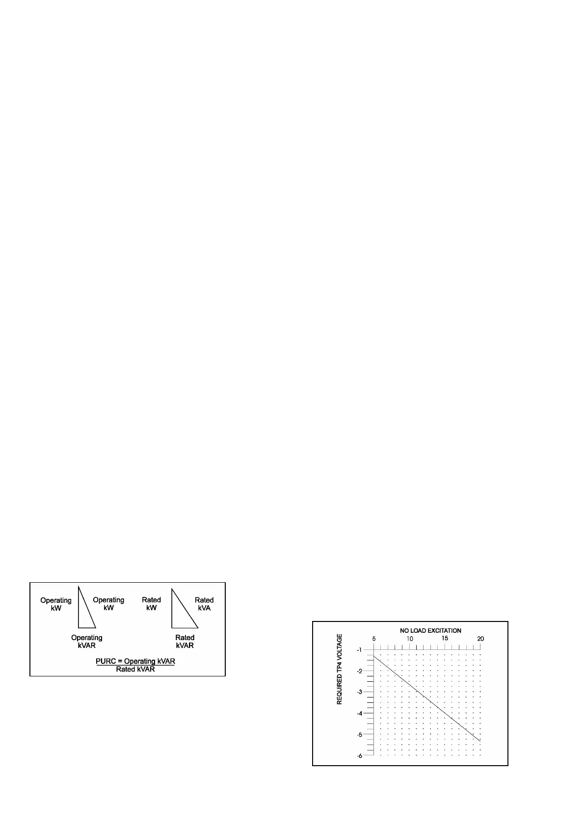
• Using the graph shown in Fig 11, adjust the low excitation
limit control XLIM to set the voltage on the test point as
indicated.
• Stop the generator and set the voltage matching selection
link to its original position.
The low excitation limiting option is now set.
Fi
. 10
Fig. 11 Low Excitation Limit Setting
 Loading...