SECTION 1
GENERAL DESCRIPTION
The Power Factor Controller (PFC3) is designed to control the
power factor reactive current (VAr) of a generator whilst
running in parallel with the mains utility.
The PFC3 is also equipped with a voltage matching facility for
use with automatic synchronisation equipment. This dispenses
with the need for motorised potentiometers and allows a lower
cost synchroniser to be used.
The PFC3 can also be connected to provide power factor
correction of the incoming mains feeder by using the generator
to supply the reactive current. A current limiting facility is
provided to prevent generator overload.
The control loop within the PFC3 has two modes of operation
to allow for the best response matching of the prime-mover
governor and the generator voltage regulator. 'Dynamic
Control' is the preferred method providing continuous
correction and high accuracy. 'Deadband Control' provides an
alternative means which allows the power factor (or VAr) to
drift between presettable limits before any correction signal is
given. This method is employed where system stability may be
a problem.
The output of the PFC3 is internally limited to restrict the
maximum (or minimum) voltage of the generator under
abnormal operating conditions. This prevents the generator
from trying to match an unrealistic mains voltage and also
limits the consumer bus-bar voltage in the event of a mains
failure.
The PFC3 incorporates an excitation limiting circuit to prevent
the generator excitation from being driven to zero (or near
zero) when operating at leading power factor.
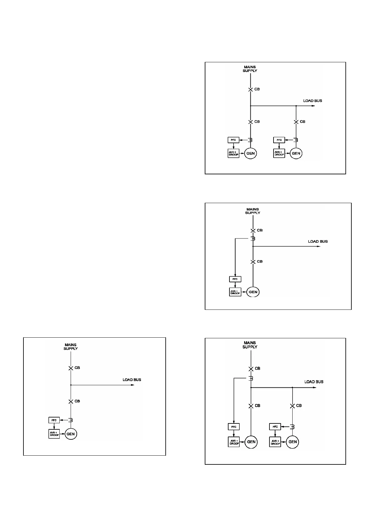
Due to its flexibility the PFC3 can be used in many different
single or multi-generator power schemes as shown in Fig 1a
through Fig 1d and the more unusual applications may not be
covered in this manual. If you are in any doubt as to the use of
the PFC3 in your application please contact your nearest
Newage International office for advice.
SINGLE GENERATOR INSTALLATION
Fi
. 1a Basic Power Factor Control
MULTIGENERATOR INSTALLATION
Fig. 1d Power Factor Correction
MULTIGENERATOR INSTALLATION
Fi
. 1b Basic Power Factor Control
Fig. 1c Power Factor Correction