26
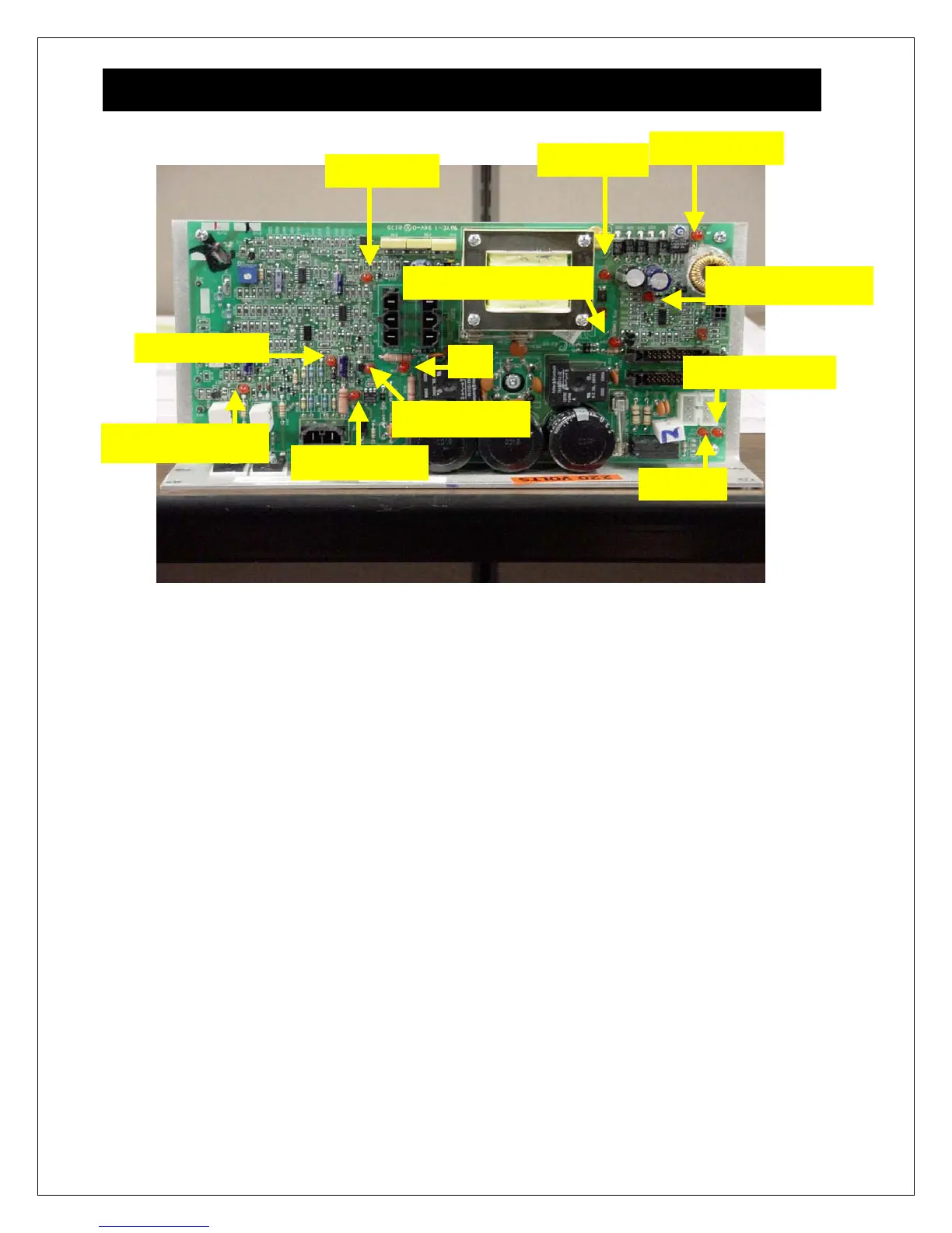
MCB (motor control board) Layout
The above LED’s are designed to help you determine at a quick glance if power is being
applied to specific components such as; display, motor and RPM sensor. Combining this with
Motor Test Mode will eliminate possible causes that may result to downtime.
The following page provides the definition for each LED.
+18V (D33)
PWM (D12)
V_CON (D34)
SPD SENSR (D30)MTR ENABLE (D24)
DOWN (D31)
UP (D32)
AC
MTR AC (D18)
MOTOR (D10)
MTR SHRT (D40)
I-LIMIT
D16