Do you have a question about the Star SP298 SERIES and is the answer not in the manual?
Guidance on selecting an optimal location for the printer, considering vibration and environment.
Steps for unpacking the printer, checking contents, and removing protective materials.
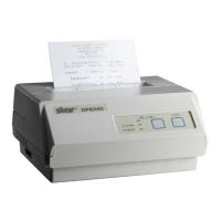
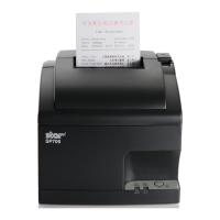
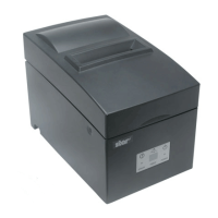
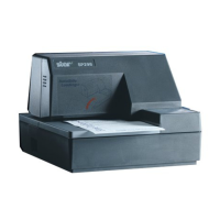
Overview of the printer's main components, buttons, and connectors.
Instructions for removing the printer cover and installing the ribbon cassette.
Procedure for removing the ribbon cassette from the printer.
Steps for connecting the printer to a power outlet and turning it on/off.
Guide to connecting the printer to a host computer via a serial interface cable.
Instructions for connecting peripheral units using a modular plug.
Procedure for inserting paper into the printer, including use of the release button.
Explanation of the AutoSide Loading feature for automatic paper positioning.
Explanation of the status indicated by the printer's power, paper out, and release indicator lights.
Details on the function of control buttons and how to produce a test print.
Procedures for adjusting dot alignment and performing a hexadecimal data dump.
Types of recoverable errors and their solutions, indicated by buzzer and lights.
Types of non-recoverable errors requiring servicing, indicated by buzzer and lights.
Explanation of data receive errors and recovery procedures based on command mode.
Detailed list of commands supported by the printer in Star mode, including character selection.
Commands for controlling line spacing, tabs, margins, and print direction.
Commands for dot graphics, page mode, and other general printer controls.
Commands for graphics downloading, peripheral device control, and slip sensor/function.
Comprehensive list of commands for ESC/POS emulation, covering various printing functions.
Details on printing system, speed, columns, dot spacing, sensors, and command modes.
Physical dimensions, weight, character sets, and matrix details for Star and ESC/POS modes.
Specifications for paper size, thickness, margins, and feed mechanisms.
Information on the AC adapter, input/output voltage, and power consumption during operation.
Procedure for accessing the printer's DIP switches by removing the document table.
Table detailing the parameters and settings for each DIP switch.
Overview of memory switches and their factory default hexadecimal codes.
Detailed pinout and signal names for the printer's serial interface.
Illustration showing a typical connection configuration between the printer and an IBM PC.
Information on the 6-pin modular connector and compatible plugs for peripheral units.
Schematic of the drive circuit for peripheral units, including notes on operation.