52
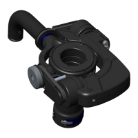
Assembly procedure
1. Remove gimbal from sled and dis-assemble all parts from top bearing portion of gimbal. Be careful to
not damage any parts as some will be re-used upon re-assembly.
2. Perform bearing cleaning or re-lubrication if required.
3. Press BRG-105420 into 305-7122 outer ring, carefully and evenly only on the outer race of the bearing
until it is fully seated.
4. Press both BRG-105427 bearings into 305-7122 outer ring carefully and evenly only on the outer race
of the bearing until they are fully seated.
5. Install 305-7124 onto 305-7101, and align screw clearance slot with screw holes in 305-7101.
6. Install and tighten SCI-4004N1210 into 305-7124 and then install and tighten SCI-4002c1210 into
same hole and tighten.
7. Thread 305-7121 into 305-7101 and fully tighten with 305-7114 wrench.
8. Install 800-7635 into 305-7121.
9. Install 305-7123 onto 305-7122 using 5x SCI-4008F1230 screws and Loctite 222. Note orientation of
ring with respect to 305-7122.
10. If gimbal is not being outtted with a volt system at this time, install 3x SCI-B014C1210 into the
threaded holes in 305-7122. Omit if a volt system is to be installed.
11. Note some newer archer 2 assemblies already tted with 315-7137 and associated parts. In this case,
assembly of 305-7158 yoke and associated parts are only required.
12. If an older archer gimbal is to be modied, assemble all handle components together as shown
noting the use of Loctite 222 where required.
13. Install completed yoke assembly onto 305-7122 using 2x 804-7109 adjustment screws and balance
gimbal as required using balance procedure and MSC-104218 spanner screwdriver bit.
14. Complete assembly by installing 2x 815-7111 caps. Omit if a volt system is to be installed.
NOTE: Perform the Archer gimbal balancing procedure found
on the next page prior to Volt installation.
Archer/Archer2