56
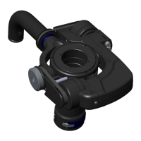
Assembly procedure
1. Remove gimbal from sled and dis-assemble main bearing housing from gimbal handle. Be careful to
not damage any parts as some will be re-used upon re-assembly.
2. Perform bearing cleaning or re-lubrication if required.
3. Install 800-7174 on to 800-7101using 8x SCI-7020S1210 screws and 222 Loctite. Note orientation of
bearing clamp.
4. Thread 800-7171 into 800-7107 and fully tighten with 305-7114-01 wrench.
5. Disassemble yoke components and then re-assemble using new 800-7175 yoke as shown noting the
use of Loctite 222 where required.
6. Remove 800-7121 sub assembly from 800-7122 by rst loosening screw SCI-A008C1210.
7. Install 800-7178 or 800-7178-01 as required and re-assemble 800-7121. Note that 800-7178-01 will
be used for sleds with a gimbal stage remote and 800-7178 for those
Sleds without.
8. Install completed yoke assembly onto 800-7107 using initially 2 x 800-7179-01 parts on either side of
yoke.
9. Balance gimbal as required using balance procedure. Note that pin- 137003 is used to install and
remove 800-7179-xx parts.
10. Complete assembly by installing 2x 815-7111 caps. Omit if a volt system is to be installed.
Ultra2, Shadow, Clipper
NOTE: Perform the gimbal balancing procedure found on
page 63, prior to Volt installation.