EasyManua.ls Logo

Steca TR A502 TT User Manual

Steca TR A502 TT
56 pages
To Next Page IconTo Next Page
Page #1 background imageLoading...
Page #1 background image
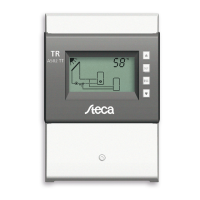
Temperature differential controller
5 inputs, 2 outputs
742.114 | Z03 | 14.50 | Subject to change due to technical improvements!
EN
Installation and operating instructions

Questions and Answers:

Steca TR A502 TT Specifications

General IconGeneral
BrandSteca
ModelTR A502 TT
CategoryThermostat
LanguageEnglish

Summary

General Safety Instructions

Proper Usage

About These Instructions

Target Audience

Identifies the intended audience for this manual, focusing on technical professionals.

Danger Levels in Warning Notices

Explains the different danger levels used in warning notices and their associated risks.

Installation

Opening / Closing the Casing

Details the procedure for removing and reattaching the front panel of the controller.

Removing the Terminal Cover

Provides safety instructions and steps for removing the terminal cover.

Mounting the Casing

Describes how to securely mount the controller unit onto a vertical surface.

Establishing the Electrical Connections

Outlines crucial safety precautions and steps for making electrical connections.

Position of the Terminals

Illustrates and describes the function of each terminal on the controller's connector block.

Preparing the Cable Openings

Explains how to prepare the casing's pre-punched openings for cable entry.

Connecting the Cables

Details the process and important considerations for connecting electrical cables to the controller.

Inserting / Removing Plastic Links

Provides instructions on how to install and remove the plastic links used for cable strain relief.

Terminal Pin Assignments

Lists terminal assignments for various system configurations and connected components.

Commissioning the Device for the First Time

Setting the Time

Guides the user through setting the current time on the controller during initial setup.

Selecting a System

Details how to select the appropriate system configuration for the installed setup.

Setting Pump 1 (Output R1)

Explains how to configure parameters for the first pump, including type and speed.

Set Pump 2 (Output R2)

Details the configuration process for the second pump, if applicable to the system.

Set the Functions

Describes how to activate and configure various functions of the controller.

Finishing Initial Commissioning

Final steps to complete the initial setup and prepare the controller for operation.

Set the Operating Mode (Off, Manual, Automatic)

Instructions for setting the controller's primary operating mode.

Structure

Casing

Describes the physical components and elements of the controller's casing.

Display

Provides an overview of the controller's display areas and their functions.

System Graphics Symbols

Explains the meaning of various symbols used in the system graphics on the display.

Settings Menu

Details the entries and structure of the controller's settings menu.

Pictograms for Functions

Describes the pictograms used to represent different functions on the controller.

Operational and Setting Values

Explains the different elements that constitute operational and setting values displayed by the controller.

Operation

Operating Buttons

Details the function and usage of each button on the controller.

Display When Operating

Explains how to interpret the display information during normal operation.

Modes of Operation

Changing the Mode of Operation

Instructions on how to switch between the controller's different operating modes.

"Off" Mode

Describes the functionality and behavior of the controller when in 'Off' mode.

"Manual" Mode

Explains how to operate the controller and its outputs manually.

"Automatic" Mode

Details the normal operating mode where the system is automatically controlled.

Settings Menu

Overview

Provides a graphic overview of the structure and navigation within the settings menu.

Calling Up the Settings Menu and Selecting a Menu Entry

Explains how to access and navigate through the controller's settings menu.

Setting the Time

Guides the user on how to set or adjust the controller's time.

Setting the System

Details the process for selecting and configuring the correct system type.

Setting the Functions

Instructions on how to set and activate specific functions within the controller.

Setting the Parameters

Explains how to access, view, and modify the controller's operational parameters.

Setting the Priority

Describes how to set the loading priority for multiple storage tanks.

Resetting to Factory Defaults

Provides instructions on how to reset all settings to their original factory default values.

Functions

Operation

Explains how to display and activate various functions on the controller.

Characteristics

Describes the configurable characteristics for different functions, such as output, temperature, and input.

Functional Description

Details the specific characteristics and behavior of each available function.

Drainback

Explains the Drainback function, its settings, and operational notes for specific systems.

Circulation

Details the Circulation function, its temperature and time control settings.

Back-up Heating

Describes the Back-up heating function, its temperature and time restrictions.

Solid Fuel Boiler

Explains the Solid fuel boiler function, including activation and speed control.

Quick Charge

Details the Quick charge function for faster storage tank loading.

Heat Quantity

Explains how the controller calculates heat quantity and CO2 savings.

Thermostat

Describes the Thermostat function for temperature-dependent switching.

Differential Thermostat

Details the Differential thermostat function based on temperature differences.

Interval

Explains the Interval function for periodic switching of the solar circuit pump.

Reduction of Stagnation Phases

Describes the function to reduce system standstill times at high temperatures.

Holiday – Recooling

Explains the Holiday – recooling function to avoid stagnation during absence.

Active Cooling

Details the Active cooling function for additional cooling.

Freeze Recirculation

Describes the Freeze recirculation function to prevent collector freezing.

Display Storage Tank Top

Explains how to display temperatures in the upper region of storage tanks.

Alarm Output

Details the Alarm output function for fault indication.
Parameters

Maximum Temperature Storage Tank 1

Sets the maximum allowable temperature for storage tank 1.

Maximum Temperature Storage Tank 2

Sets the maximum allowable temperature for storage tank 2.

Maximum Temperature Swimming Pool

Sets the maximum allowable temperature for the swimming pool.

Switch-on Temperature Difference Solar Circuit 1

Defines the temperature difference for switching on the solar circuit 1.

Switch-off Temperature Difference Solar Circuit 1

Defines the temperature difference for switching off the solar circuit 1.

Switch-on Temperature Difference Solar Circuit 2

Defines the temperature difference for switching on the solar circuit 2.

Switch-off Temperature Difference Solar Circuit 2

Defines the temperature difference for switching off the solar circuit 2.

Switch-on Temperature Difference External Heat Exchanger

Sets the temperature difference for switching on the external heat exchanger.

Switch-off Temperature Difference External Heat Exchanger

Sets the temperature difference for switching off the external heat exchanger.

Maximum Collector Temperature

Sets the maximum allowable temperature for the collector.

Minimum Collector Temperature

Sets the minimum allowable temperature for the collector.

Switch-on Temperature Difference Heating Return Increase

Defines the temperature difference for switching on the heating return increase.

Switch-off Temperature Difference Heating Return Increase

Defines the temperature difference for switching off the heating return increase.

Maximum Temperature Loading Circuit

Sets the maximum temperature for the loading circuit.

Minimum Temperature Loading Circuit

Sets the minimum temperature for the loading circuit.

Loading Strategy Storage Tank 1

Configures the loading strategy for storage tank 1 (e.g., efficiency, temperature).

Loading Strategy Storage Tank 2

Configures the loading strategy for storage tank 2 (e.g., efficiency, temperature).

Pump Type R1

Selects the pump type (AC or HE) for output R1.

Pump Type R2

Selects the pump type (AC or HE) for output R2.

Control of the Storage Tank Loading Valve

Sets the control mode (normal/inverted) for the storage tank loading valve.

Control of the Zone Loading Valve

Sets the control mode (normal/inverted) for the zone loading valve.

Control of the Return Increase

Sets the control mode (normal/inverted) for the return increase.

Dismantling and Disposal

Info Messages

Troubleshooting

General Faults

Lists common faults, their possible causes, and recommended remedies for the controller.

Error Messages

Explains specific error messages displayed by the controller and their troubleshooting steps.

Checking the Pt1000 Temperature Sensor

Provides a guide and resistance table for testing the Pt1000 temperature sensor.

Technical Data

Controller

Presents detailed technical specifications for the controller, including inputs, outputs, and physical data.

Cable Specifications

Outlines the specifications for mains and sensor cables compatible with the controller.

Exclusion of Liability

Legal Guarantee

Notes