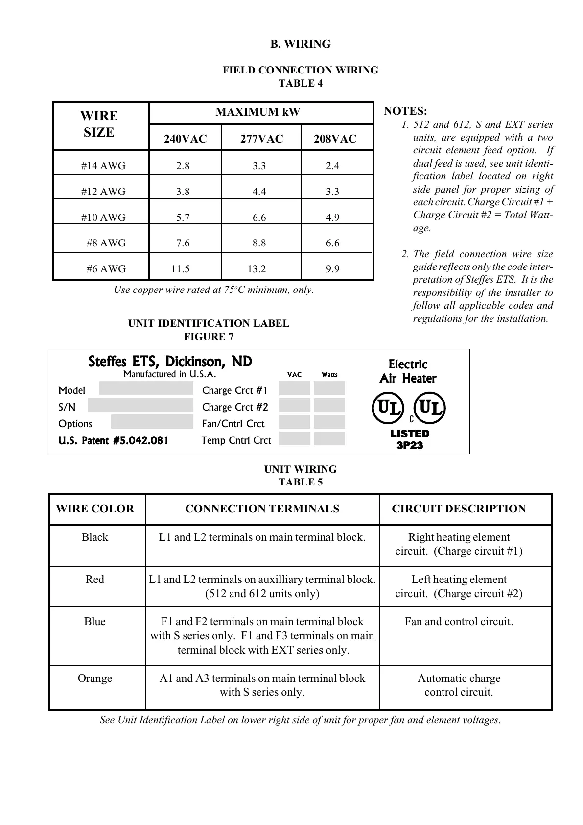
B. WIRING
FIELD CONNECTION WIRING
TABLE 4
UNIT WIRING
TABLE 5
WIRE COLOR CONNECTION TERMINALS CIRCUIT DESCRIPTION
Black L1 and L2 terminals on main terminal block. Right heating element
circuit. (Charge circuit #1)
Red L1 and L2 terminals on auxilliary terminal block. Left heating element
(512 and 612 units only) circuit. (Charge circuit #2)
Blue F1 and F2 terminals on main terminal block Fan and control circuit.
with S series only. F1 and F3 terminals on main
terminal block with EXT series only.
Orange A1 and A3 terminals on main terminal block Automatic charge
with S series only. control circuit.
See Unit Identification Label on lower right side of unit for proper fan and element voltages.
NOTES:
1. 512 and 612, S and EXT series
units, are equipped with a two
circuit element feed option. If
dual feed is used, see unit identi-
fication label located on right
side panel for proper sizing of
each circuit. Charge Circuit #1 +
Charge Circuit #2 = Total Watt-
age.
2. The field connection wire size
guide reflects only the code inter-
pretation of Steffes ETS. It is the
responsibility of the installer to
follow all applicable codes and
regulations for the installation.
MAXIMUM kW
240VAC 277VAC 208VAC
#14 AWG 2.8 3.3 2.4
#12 AWG 3.8 4.4 3.3
#10 AWG 5.7 6.6 4.9
#8 AWG 7.6 8.8 6.6
#6 AWG 11.5 13.2 9.9
WIRE
SIZE
UNIT IDENTIFICATION LABEL
FIGURE 7
Model Charge Crct #1
S/N Charge Crct #2
Options Fan/Cntrl Crct
U.S. Patent #5.042.081U.S. Patent #5.042.081
U.S. Patent #5.042.081U.S. Patent #5.042.081
U.S. Patent #5.042.081 Temp Cntrl Crct
ElectricElectric
ElectricElectric
Electric
Air HeaterAir Heater
Air HeaterAir Heater
Air Heater
Steffes ETS, Dickinson, NDSteffes ETS, Dickinson, ND
Steffes ETS, Dickinson, NDSteffes ETS, Dickinson, ND
Steffes ETS, Dickinson, ND
Manufactured in U.S.A.
VACVAC
VACVAC
VAC
WattsWatts
WattsWatts
Watts
U
L
U
L
LISTEDLISTED
LISTEDLISTED
LISTED
3P233P23
3P233P23
3P23
C
Use copper wire rated at 75
o
C minimum, only.