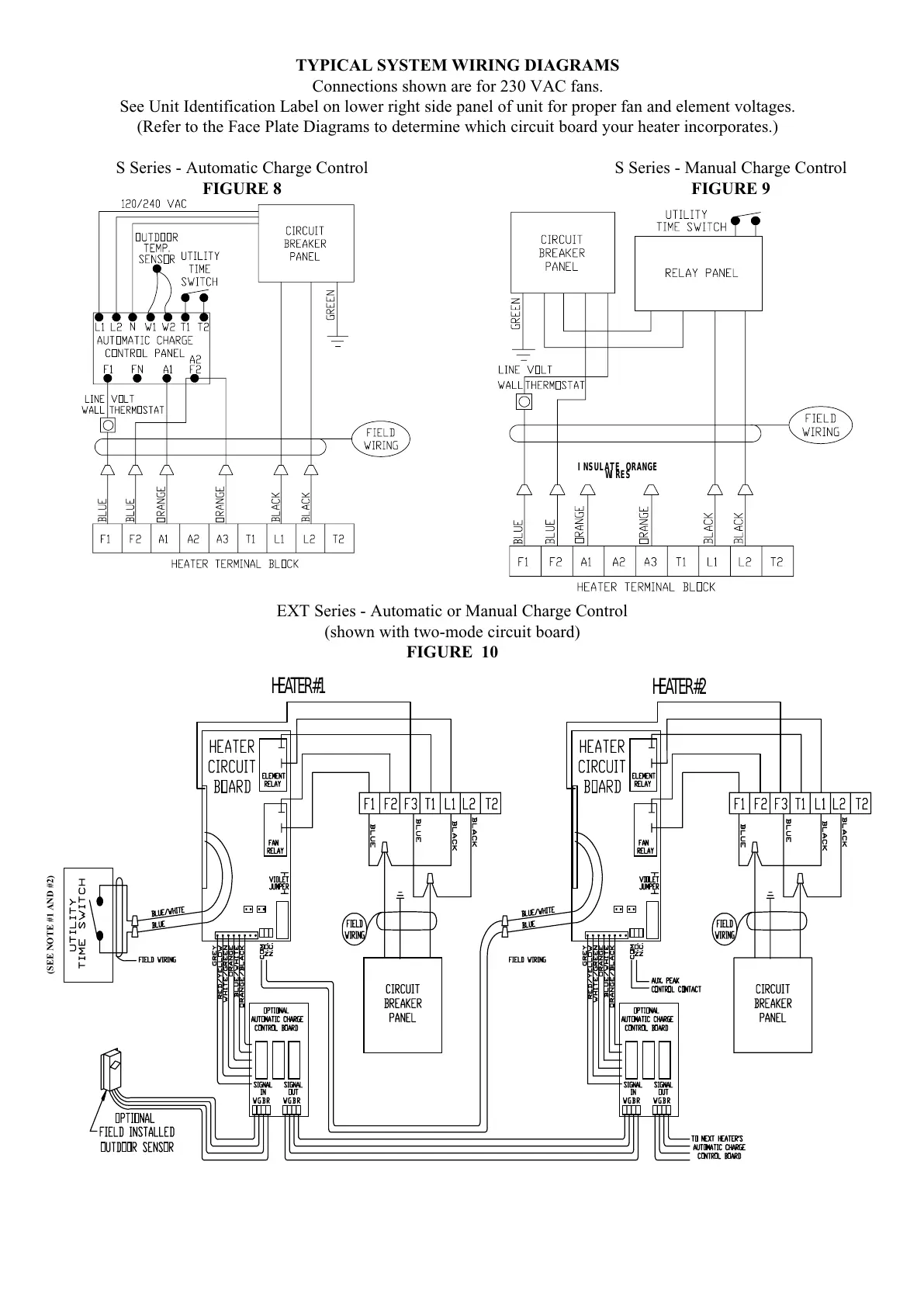
EXT Series - Automatic or Manual Charge Control
(shown with two-mode circuit board)
FIGURE 10
HEATER #1
HEATER #2
TYPICAL SYSTEM WIRING DIAGRAMS
Connections shown are for 230 VAC fans.
See Unit Identification Label on lower right side panel of unit for proper fan and element voltages.
(Refer to the Face Plate Diagrams to determine which circuit board your heater incorporates.)
S Series - Automatic Charge Control S Series - Manual Charge Control
FIGURE 8 FIGURE 9
INSULATE ORANGE
WIRES
(SEE NOTE #1 AND #2)