The EXT series can be configured in many ways. Due to the wide variety of setup methods and options, it
may be necessary to consult with your sales representative for the operation instructions of your
heating system.
Several control devices can be used for core charging. Different combinations of these devices will provide
for optimal unit function based upon utility needs, home characteristics, and installation requirements.
Rocker switches, if unit is equipped, are located on the front control panel and will vary the level of charge
that is stored in the unit's brick core. The HEAT STORAGE rocker switch can be set in the OFF position to
minimize the amount of heat stored or in the ON position to activate the CHARGE LEVEL rocker switch.
The CHARGE LEVEL switch can be placed in the LOW/AUTO position for applications using automatic
charge control. With the addition of this option, core temperature is automatically regulated in relation to
outdoor air temperature. Override of the automatic charge controller can occur by setting the CHARGE
LEVEL rocker switch to MEDIUM or HIGH.
Automatic charge control may also be configured without rocker switches. In these installations, core
temperature level is solely controlled by an outdoor air temperature sensor, by the utility, or self regulated
by the amount of heat being required to satisfy the room's requirements.
For applications without automatic charge control, LOW/AUTO position is normally used during the
early spring and late fall. Setting the CHARGE LEVEL switch to positions MEDIUM or HIGH will
increase charge levels for colder weather conditions.
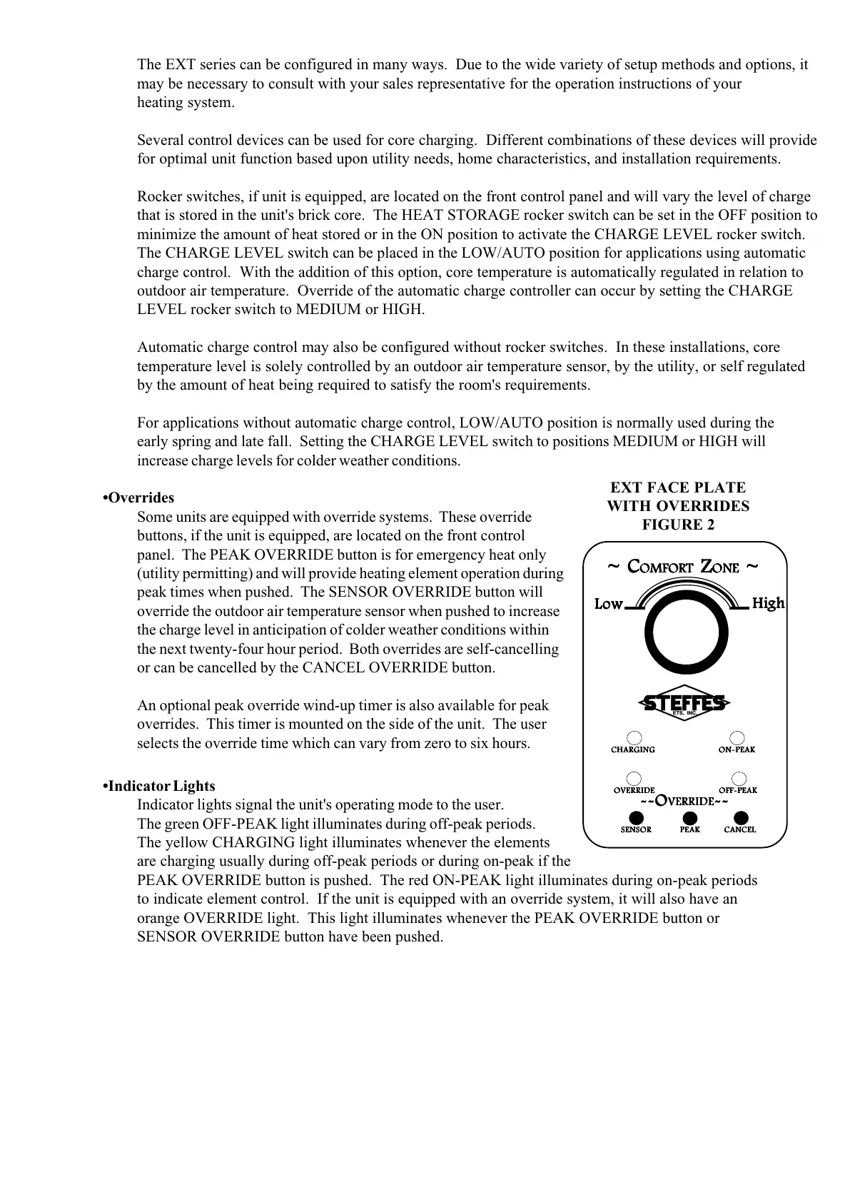
•Overrides
Some units are equipped with override systems. These override
buttons, if the unit is equipped, are located on the front control
panel. The PEAK OVERRIDE button is for emergency heat only
(utility permitting) and will provide heating element operation during
peak times when pushed. The SENSOR OVERRIDE button will
override the outdoor air temperature sensor when pushed to increase
the charge level in anticipation of colder weather conditions within
the next twenty-four hour period. Both overrides are self-cancelling
or can be cancelled by the CANCEL OVERRIDE button.
An optional peak override wind-up timer is also available for peak
overrides. This timer is mounted on the side of the unit. The user
selects the override time which can vary from zero to six hours.
•Indicator Lights
Indicator lights signal the unit's operating mode to the user.
The green OFF-PEAK light illuminates during off-peak periods.
The yellow CHARGING light illuminates whenever the elements
are charging usually during off-peak periods or during on-peak if the
PEAK OVERRIDE button is pushed. The red ON-PEAK light illuminates during on-peak periods
to indicate element control. If the unit is equipped with an override system, it will also have an
orange OVERRIDE light. This light illuminates whenever the PEAK OVERRIDE button or
SENSOR OVERRIDE button have been pushed.
EXT FACE PLATE
WITH OVERRIDES
FIGURE 2
~ C~ C
~ C~ C
~ C
OMFOROMFOR
OMFOROMFOR
OMFOR
TT
TT
T
Z Z
Z Z
Z
OO
OO
O
NENE
NENE
NE
~ ~
~ ~
~
LoLo
LoLo
Lo
ww
ww
w
HiHi
HiHi
Hi
ghgh
ghgh
gh
SENSORSENSOR
SENSORSENSOR
SENSOR
PEAKPEAK
PEAKPEAK
PEAK
CANCELCANCEL
CANCELCANCEL
CANCEL
--O--O
--O--O
--O
VERRIDEVERRIDE
VERRIDEVERRIDE
VERRIDE
----
----
--
CHARGINGCHARGING
CHARGINGCHARGING
CHARGING
OO
OO
O
N-PEAKN-PEAK
N-PEAKN-PEAK
N-PEAK
OO
OO
O
VERRIDEVERRIDE
VERRIDEVERRIDE
VERRIDE
OFF-PEAKOFF-PEAK
OFF-PEAKOFF-PEAK
OFF-PEAK