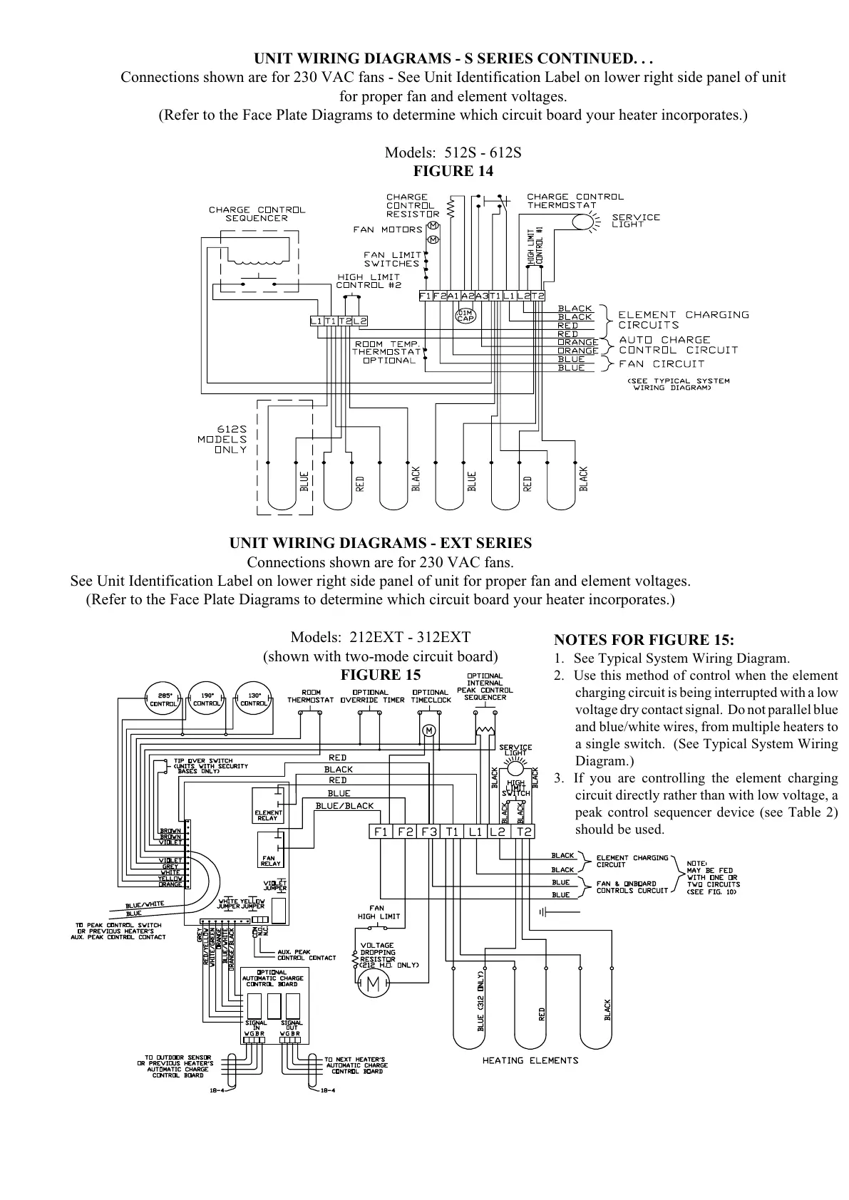
UNIT WIRING DIAGRAMS - S SERIES CONTINUED. . .
Connections shown are for 230 VAC fans - See Unit Identification Label on lower right side panel of unit
for proper fan and element voltages.
(Refer to the Face Plate Diagrams to determine which circuit board your heater incorporates.)
Models: 512S - 612S
FIGURE 14
UNIT WIRING DIAGRAMS - EXT SERIES
Connections shown are for 230 VAC fans.
See Unit Identification Label on lower right side panel of unit for proper fan and element voltages.
(Refer to the Face Plate Diagrams to determine which circuit board your heater incorporates.)
Models: 212EXT - 312EXT
(shown with two-mode circuit board)
FIGURE 15
NOTES FOR FIGURE 15:
1. See Typical System Wiring Diagram.
2. Use this method of control when the element
charging circuit is being interrupted with a low
voltage dry contact signal. Do not parallel blue
and blue/white wires, from multiple heaters to
a single switch. (See Typical System Wiring
Diagram.)
3. If you are controlling the element charging
circuit directly rather than with low voltage, a
peak control sequencer device (see Table 2)
should be used.