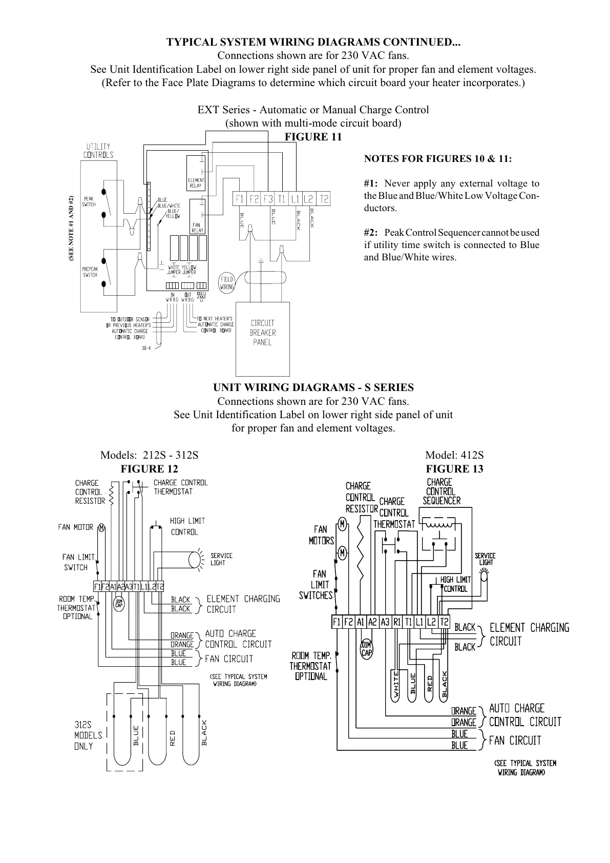
UNIT WIRING DIAGRAMS - S SERIES
Connections shown are for 230 VAC fans.
See Unit Identification Label on lower right side panel of unit
for proper fan and element voltages.
Models: 212S - 312S Model: 412S
FIGURE 12 FIGURE 13
TYPICAL SYSTEM WIRING DIAGRAMS CONTINUED...
Connections shown are for 230 VAC fans.
See Unit Identification Label on lower right side panel of unit for proper fan and element voltages.
(Refer to the Face Plate Diagrams to determine which circuit board your heater incorporates.)
EXT Series - Automatic or Manual Charge Control
(shown with multi-mode circuit board)
FIGURE 11
NOTES FOR FIGURES 10 & 11:
#1: Never apply any external voltage to
the Blue and Blue/White Low Voltage Con-
ductors.
#2: Peak Control Sequencer cannot be used
if utility time switch is connected to Blue
and Blue/White wires.
(SEE NOTE #1 AND #2)