®
2 Mechanical structure
© F. Stephan GmbH SA-112-0106V1.0-WEM-GB 13
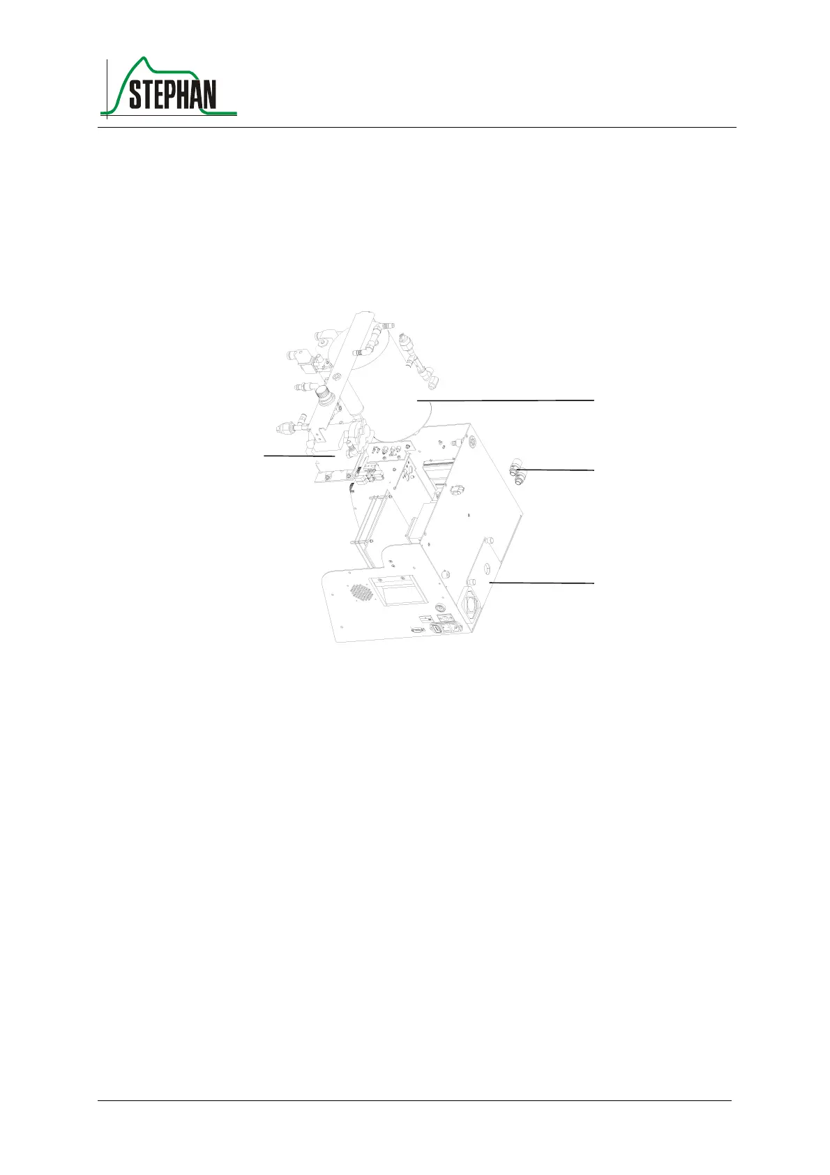
The entire pneumatic system is accommodated in the basic housing. Only
the double flowmeter is in the front housing.
The pneumatic system consists of the compressor, the fresh gas reservoir
and its control valves. The pressure switches for detecting the intake
pressure are firmly integrated in the pneumatic system
Fig. 7: pneumatic components
1 compressor 2 fresh gas reservoir
3 gas inlets 4 service flap
The patient part is connected to the basic device from the front.
The patient part is held in position by the guide rail.
2
3
4
1