DM422T Digital Stepper Drive User Manual
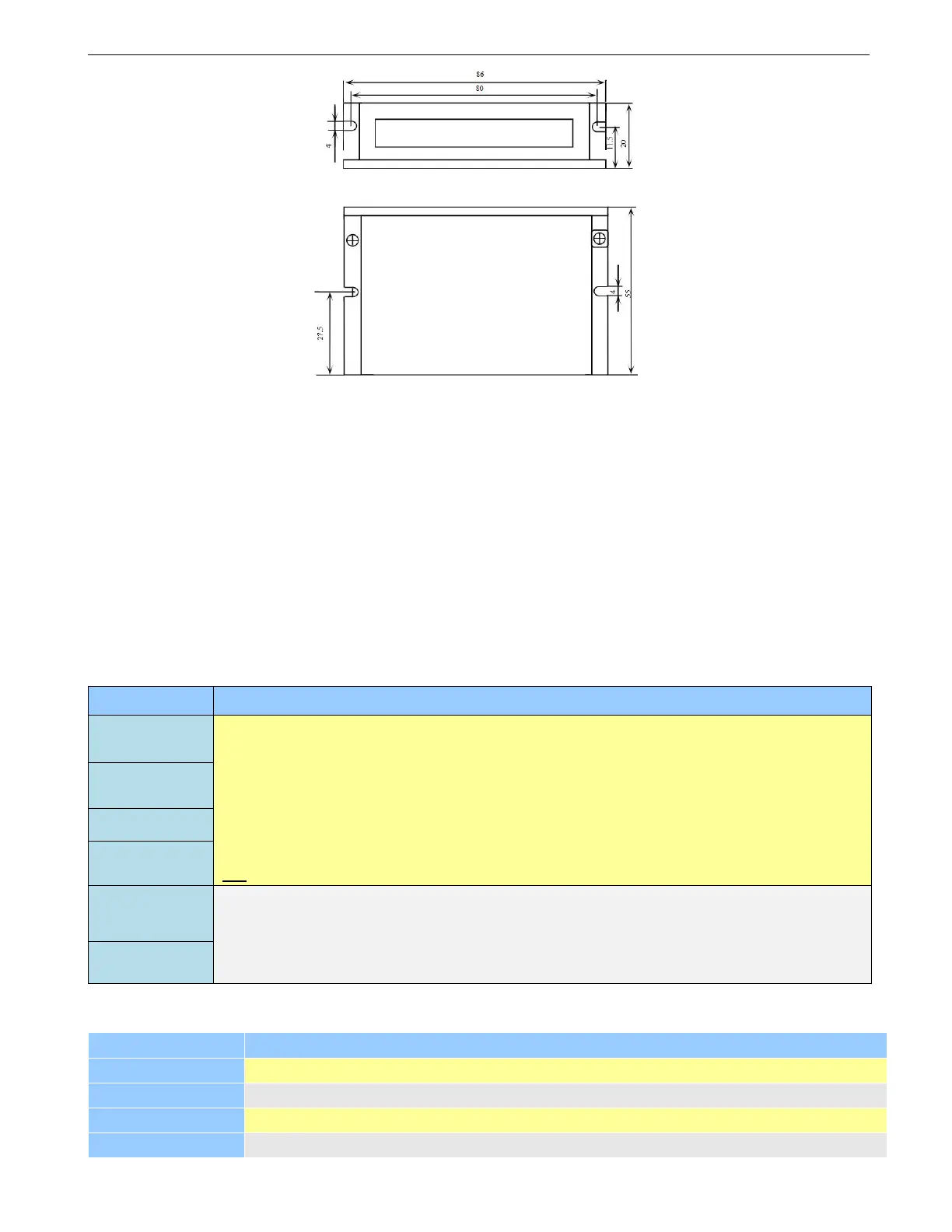
Figure 1 Mechanical specifications
Side mounting recommended for better heat dissipation
2.4 Elimination of Heat
DM422T reliable working temperature should be < 40℃ (109°F)
It is recommended to use automatic idle-current mode to reduce motor heating. That means set the SW4
pin of DIP switch at “OFF” position.
It is recommended to mount the drive vertically to maximize heat sink area. Use forced cooling method
to cool if necessary.
3. Connection Pin Assignments and LED Indication
3.1 Control Connector
Pulse and Direction Connection:
(1) Optically isolated, high level 4.5-5V or 24V, low voltage 0-0.5V
(2) Maximum 500 KHz input frequency
(3) Duty cycle is recommended 50%
(4) DIR signal requires advance PUL signal minimum 5 μs in single pulse mode
(5) The factory setting of control signal voltage is 24V, must set dip switch if it is 5V
(6) Enable Connection: default no connection
(1) Maximum 30V/100mA output
(2) Sinking or sourcing
(3) The resistance between ALM+ and ALM- is low impedance as default, and will change
to high when the drive goes into error protection.
3.2 Motor and Power Supply Connector
Power supply ground connection.
Power supply positive connection. Suggest 24/36VDC power supply voltage
Motor Phase A connections. Connect motor A+ wire to A+ Pin; motor A- wire to A-
Motor Phase B connections. Connect motor B+ wire to B+ Pin; motor B- wire to B-