DM422T Digital Stepper Drive User Manual
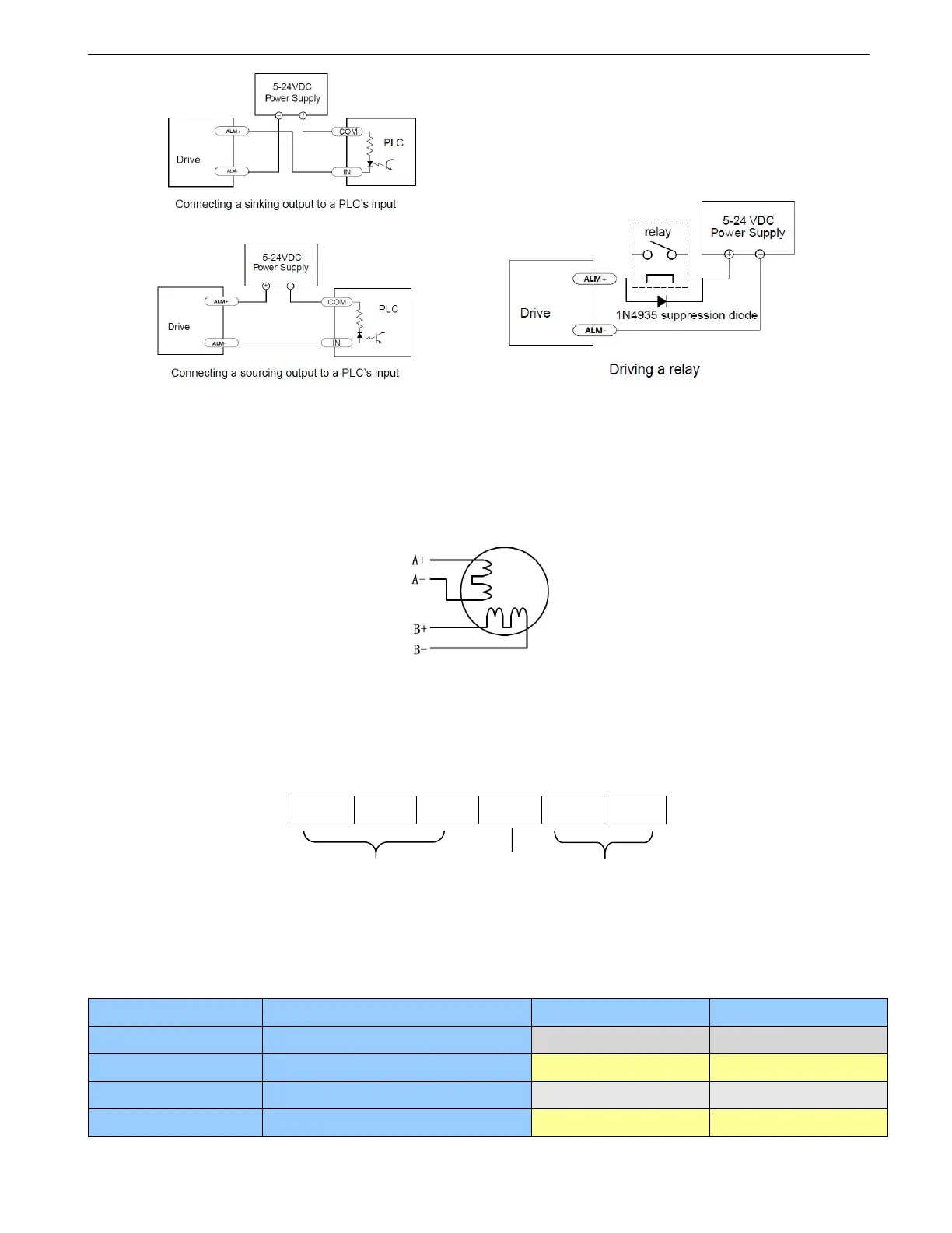
Figure 6 Fault Connection
5. Motor Connection
The DM422T can drive 2-phase and 4-pahse bipolar hybrid stepper motors.
The 4 lead motors are the least flexible and easy to connect. The output current from drive that is multiply the
specified phase current by 1.4 to determine the peak output current.
Figure 7 4-lead Motor Connections
6. DIP Switch Configurations
The DM422T has 6-bit, 4-bit DIP switch and a 1-bit DIP switch. The first 6-bit is used to configure settings of
micro step resolution, output current, motor standstill current as shown below.
The 5V/24V dip switch is located on the top, used to configure the voltage of control signals. For the safety of
optically coupled, the factory setting is 24V.
6.1 Microstep Resolution Configurations
Microstep resolution is set by SW5, 6 of the DIP switches as shown in the following table. Note: “default”
means the parameters can be set by GUI tuning software.
Steps/rev.(for 1.8°motor)